


364861-UIM-H-0712
Johnson Controls Unitary Products 37
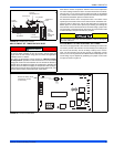
FURNACE CONTROL DIAGNOSTICS
The furnace has built-in, self-diagnostic capability. A blinking LED light
on the control board can flash red, green or amber to indicate various
conditions. The control continuously monitors its own operation and the
operation of the system. If a failure occurs, the LED light will indicate
the failure code.
The SLOW flash speed is two seconds on and two seconds off.
The other flash codes listed below have the following timing: LED light
will turn on for 1/3 second and off for 1/3 second. This pattern will be
repeated the number of times equal to the code. There will be a two-
second pause between codes. For example, the six red flash code will
flash the LED light on and off six times, then will be off for two seconds.
This pattern will repeat as long as the fault condition remains. The con-
tinuous flash codes listed below will flash the LED light on and off con-
tinuously, with no breaks or longer pauses.
SLOW GREEN FLASH: Normal operation, no thermostat calls.
SLOW AMBER FLASH: Normal operation with call for heat.
LED STEADY OFF – If the LED light does not flash at all, check for
power to the board and check for a blown fuse on the board. If the
board is properly powered and the fuse is not blown, the control board
may need to be replaced.
STEADY ON ANY COLOR: Control failure. Turn power to the furnace
off and back on. If the fault code returns, the control board must be
replaced. The control board is not field-repairable.
CONTINUOUS GREEN FLASH: Twinning error, incorrect 24V phasing
or no power to twinned unit. Check twinning wiring. Confirm that both
twinned units have power.
CONTINUOUS AMBER FLASH: Flame sense current is below 1.5
microamps. Check and clean flame sensor. Check for proper gas flow.
Verify that current is greater than 1.5 microamps at flame current test
pad.
1 RED FLASH: This indicates that flame was sensed when there was
not a call for heat. The control will turn on both the inducer motor and
supply air blower. Check for a leaking or slow-closing gas valve.
2 RED FLASHES: This indicates that the pressure switch is closed
when it should be open. The control confirms that the pressure switch
contacts are open at the beginning of each heat cycle and will not let
the ignition sequence continue if the pressure switch contacts are
closed when they should be open. Check for a faulty pressure switch or
miswiring.
3 RED FLASHES: This indicates the pressure switch contacts are open
when they should be closed. Check for faulty inducer, blocked vent
pipe, broken pressure switch hose, disconnected pressure switch or
inducer wires or faulty pressure switch.
4 RED FLASHES: This indicates that the main limit switch has opened
its normally closed contacts. The control will operate the supply air
blower and inducer while the open limit condition exists. Check for a
dirty filter, improperly sized duct system, incorrect blower speed setting,
incorrect firing rate, loose limit switch wiring or faulty blower motor.
If the limit switch has not closed within five minutes, the control will
assume that the blower is not functioning, will start a hard lockout and
will begin to flash the 11 Red Flashes error code. Power will have to be
cycled off and on to reset the control after the problem has been cor-
rected. See “11Red Flashes” description below.
If the main limit switch opens five times within a single call for heat, the
control will also indicate 4 Red Flashes and will enter a one-hour soft
lockout.
5 RED FLASHES: This fault is indicated if the normally closed rollout
switch opens. The rollout control is manually reset. Check for proper
combustion air, proper inducer operation, and primary heat exchanger
failure or burner problem. The control will enter a hard lockout and
power will have to be cycled off and on to reset the control after the
problem has been corrected.
6 RED FLASHES: This indicates that while the unit was operating, the
pressure switch opened four times during the call for heat. Check for
faulty inducer, blocked vent pipe or faulty pressure switch. The furnace
will lock out for one hour and then restart.
7 RED FLASHES: This fault code indicates that the flame could not be
established during three trials for ignition. Check that the gas valve
switch is in the ON position. Check for low or no gas pressure, faulty
gas valve, dirty or faulty flame sensor, faulty hot surface ignitor, loose
wires or a burner problem. The furnace will lock out for one hour and
then restart.
8 RED FLASHES: This fault is indicated if the flame is lost five times
(four recycles) during the heating cycle. Check for low gas pressure,
dirty or faulty flame sensor or faulty gas valve. The furnace will lock out
for one hour and then restart.
9 RED FLASHES: Indicates reversed line voltage polarity, grounding
problem or reversed low voltage transformer wires. Both heating and
cooling operations will be affected. Check polarity at furnace and
branch. Check furnace grounding. Check that flame probe is not
shorted to chassis. The furnace will not start the ignition sequence until
this problem is corrected.
10 RED FLASHES: Gas valve energized with no call for heat. The main
blower and inducer blower will run and no ignition sequence will be
started as long as this condition exists. Check gas valve and gas valve
wiring.
11 RED FLASHES: This indicates that the main limit switch has opened
its normally-closed contacts and has remained open for more than five
minutes. This condition is usually caused by a failed blower motor or
blower wheel. The control will enter a hard lockout and power will have
to be cycled off and on to reset the control after the problem has been
corrected.
4 AMBER FLASHES: The control is receiving a “Y” signal from the
thermostat without a “G” signal. The furnace will operate normally in
both heating and cooling, but this fault code will be displayed in order to
alert the user that there is a wiring problem. Verify that the “G” wire from
the thermostat is connected properly.
SOFT LOCKOUT: This control includes a soft lockout that will reset
automatically after one hour. This provides protection to an unoccupied
structure if a temporary condition exists causing a furnace malfunction.
An example of this is a temporary interruption in gas supply that would
prevent the furnace from lighting. The control will keep trying to light
each hour and will resume normal operation if the gas supply is
restored.
HARD LOCKOUT: Some fault conditions result in a hard lockout, which
requires power to the control to be turned off and then back on to reset
the control. The control will not automatically restart.
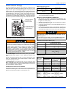
IGNITION CONTROL FLAME SENSE LEVELS
Normal flame sense current is approximately
3.7 microamps DC (µa)
Low flame signal warning starts at 1.5 microamps.
Low flame signal control lockout point is
0.1 microamps DC (µa)