


61
OPTIONAL INSTALLATIONS/SETTINGS
10
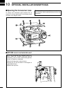
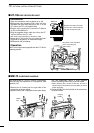
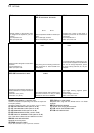
■ UT-106
DSP RECEIVER UNIT
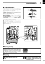
D Installation
➀Open the transceiver case as shown on p. 59.
➁Remove the 4-pin connector (P251) from J1413 on
the MAIN unit (top side) and plug it into J1 of the
UT-106 on the PLL unit (bottom side).
➂Plug the 4-pin connector (P1) from the UT-106 into
J1413 on the MAIN unit.
➃Plug the supplied ribbon cable into J3 on the UT-
106 and J253 on the PLL unit.
•Be careful of the orientation of the ribbon cable.
➄Attach the UT-106 to the PLL unit, using the exist-
ing guide for alignment, as illustrated at right.
➅Reassemble the transceiver.
DOperation
Refer to the instructions supplied with the UT-106 for
operating details.
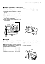
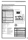
■ MB-72
CARRYING HANDLE
The optional MB-72
CARRYING HANDLE
is convenient
when carrying the transceiver for DX’peditions, field
operation, etc.
➀Remove the 2 screws from the right side of the
transceiver as shown below.
➁Replace those with 2 supplied screws plus rubber
feet and additionally attach 2 more supplied
screws (including rubber feet) as shown below.
•When replacing the 2 screws at the rear, be sure to
squeeze the top and bottom covers together to ensure
proper alignment.
➂Attach the MB-72 to the left side of the transceiver
as shown below.
rubber
feet
carrying
handle
J1
P251
MAIN unit
UT-106
unit position
PLL unit
Remove the J1431 connector
from the PLL unit and replace
with the UT-106 connector
Be careful of the orientation
when connecting the
ribbon cable.
P1
J1431
P253
P1
J3
J1