


7
1
PANEL DESCRIPTION
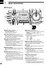
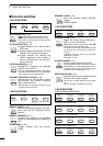
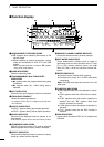
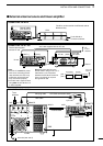
■ Function display
qNARROW/WIDE FILTER INDICATORS
➥ “ã” appears when selecting AM narrow or FM
narrow modes.
➥ When installing an optional narrow filter, narrow
mode can be selected in CW, RTTY and SSB
modes.
•When the SSB wide filter is installed, “ç” appears
during wide mode selection.
w MODE INDICATORS
Show the operating mode.
ePROGRAMMABLE/1 MHz TUNING STEP
INDICATORS
➥➌a appears when the programmable tuning step
is selected.
➥➌b appears when the 1 MHz tuning step is
selected.
rSPLIT INDICATOR
Shows that the split frequency function is activated.
tFREQUENCY READOUT
Shows the operating frequency.
•“C” appears in place of the 1 Hz digit when the call chan-
nel is selected.
yDUPLEX INDICATORS
➥ “DUP+” appears during plus duplex operation.
➥ “DUP–” appears during minus duplex operation.
uBLANK INDICATOR
Shows that the displayed memory channel is not
programmed.
•This indicator appears both in VFO and memory modes.
iVFO/MEMORY INDICATORS
VFO A or B appears when VFO mode is selected;
MEMO appears when memory mode is selected.
oSELECT INDICATOR
Shows that the displayed memory channel is desig-
nated as a select memory channel.
!0MEMORY CHANNEL NUMBER READOUT
Shows the selected memory channel number.
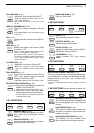
!1DOT MATRIX INDICATORS
These alphanumeric readouts show a variety of
information such as current functions of the “F” keys
[F1] to [F3], memory channel names, set mode
items, etc. See p. 68 for an overview of these indi-
cators.
!2METER READOUTS
➥ Functions as an S-meter while receiving.
➥ Functions as a power, ALC or SWR meter while
transmitting.
Note:The SWR meter does not function in the 144
MHz band.
!3FUNCTION INDICATORS
➥ “NB” appears when the noise blanker is activat-
ed.
➥ “VOX” appears when the VOX function is select-
ed.
➥ “F-BK” appears when full break-in operation is
selected and only “BK” appears when semi
break-in operation is selected.
➥ “COM” appears when the speech compressor is
activated.
➥ “FAGC” appears when the fast AGC function is
selected.
!4DSP INDICATORS
Appear when the optional DSP unit is installed and
activated.
N W R SPL
LSB
DSP
NB VOX F-BK COM F
S
CH
VFO A
DUP
VFO B
MEMO
AGC
ALC
SWR PO
S1
1 1.5 2 3 5
53792040
10
∞
60dB
USB CW R
TT
Y
AMWFM TSQL
BLANK
ANF
NR
qw r
t
y
u
o
!1
!2
!3
!4
i
!0
ea
eb
M1
SPL
A/B
A=B