


2
1
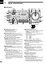
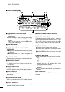
PANEL DESCRIPTION
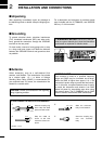
panel. DO NOT connect 2 microphones simultaneously.
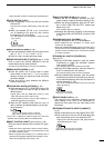
!2LOCK SWITCH [LOCK]
➥Push momentarily to turn the dial lock function
ON and OFF.
•The dial lock function electronically locks the main
dial.
➥When the optional UT-102
VOICE SYNTHESIZER
UNIT
is installed (p. 52), push for 2 sec. to have
the frequency, etc. announced.
•UT-102 operation can be adjusted in initial set mode
(pgs. 53, 54).
!3DISPLAY SWITCH [DISP] (p. 68)
➥Push momentarily to select one of the three menu
sets: M1 to M4, S1 to S4 and G1 to G4.
➥Push for 2 sec. to select quick set mode.
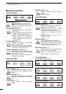
!4FUNCTION SWITCHES [F1]/[F2]/[F3] (pgs. 3, 4, 68)
Push to select the function indicated in the dot
matrix display above these switches.
•Functions vary depending on the menu set selected.
!5MENU SWITCH [MENU] (p. 68)
➥
P
ush this switch one or more times to select
menus within a menu set (M, S or G), or push to
advance through the quick set mode and initial
set mode displays.
➥Push and hold to jump between two different
function menu sets.
!6RIT/SUB DIAL SWITCH [RIT/SUB] (p. 20)
➥Push to toggle the RIT or SUB DIAL function ON
and OFF—initial set mode is used to select the
desired action*.
•Lights green when the SUB DIAL function is ON;
lights red when the RIT function is ON.
•Use the [M-CH] control to vary the RIT frequency or
SUB DIAL frequency (see above).
➥When the RIT function is ON, push for 2 sec. to
add or subtract the shifted frequency to the oper-
ating frequency.
*Even if RIT is selected in initial set mode, RIT cannot be
selected when operating AM, FM or WFM modes.
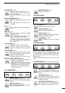
!7SHIFT CONTROL [SHIFT] (outer control; p. 20)
Shifts the center frequency of the receiver’s IF pass-
band.
•Rotate the control clockwise to shift the center frequen-
cy higher, or rotate the control counterclockwise to shift
the center frequency lower.
•When the graphic menu display (
G2) is selected, the IF
passband is graphically displayed and changes in accor-
dance with the [SHIFT] control (see p. 20).
!8M-CH CONTROL [M-CH] (inner control)
➥
When the RIT or SUBDIAL functions are OFF,
rotate to select a memory channel number (p. 35).
➥Shifts the receive frequency while the RIT func-
tion is ON in SSB, CW and RTTY modes (see
below and p. 20).
•RIT variable range is ± 9.99 kHz
➥Changes the operating frequency in the selected
tuning steps while the SUB DIAL function is ON
(p. 18).
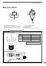
!9HEADPHONE JACK [PHONES] (p. 12)
Accepts headphones with 4–16 Ω impedance.
•When headphones are connected, no receive audio
comes from the speaker.
•When the PHONES/SPEAKER switch on the back of the
front panel is set to the [SPEAKER] position, an external
speaker can be connected. This is convenient for mobile
or outdoor operation.
@0TUNER/CALL SWITCH [TUNER/CALL]
(pgs. 26, 27)
➥During HF/50 MHz operation, push this switch
momentarily to toggle the automatic antenna
tuner function ON/OFF.
•An optional antenna tuner must be connected.
➥During HF/50 MHz operation, push this switch for
2 sec. to manually tune the antenna.
•An optional antenna tuner must be connected.
➥During 144/430 MHz operation, push this switch
momentarily to select the call channel (or the pre-
vious channel/frequency when the call channel is
already selected). (p. 39)
•“C1” is the 144 MHz call channel and “C2” is the 430
MHz call channel.
@1
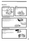
FRONT PANEL LATCH (p. 10)
Pull away from the transceiver (towards yourself
when looking at the front of the transceiver) to
detach the front panel from the main body of the
transceiver.
@2P
REAMP/ATTENUATOR SWITCH [P.AMP/ATT]
(p. 21)
➥Push momentarily to turn the preamp ON or OFF.
➥Push and hold to turn the 20 dB attenuator ON;
push momentarily to turn the attenuator OFF.
•Lights green when the preamp is ON; lights red when
the 20 dB attenuator is ON.
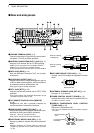
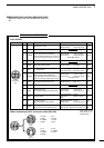
LOCK
Lights while the lock
function is activated.
RIT
SUB
Lights red while the RIT function is activated;
green while the SUB DIAL function is activated.
TUNER/CALL
Lights while the automatic
tuning function is activated.
P.AMP/ATT
Lights green while the preamp is activated;
lights red while the attenuator is activated.