


46
6
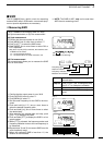
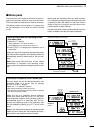
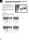
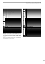
REMOTE JACK (CI-V) INFORMATION
*
1
When wide or normal operation is available, add “00” for wide oper-
ation or “01” for normal operation; when normal or narrow operation
is available, add “00” for normal operation or “01” for narrow opera-
tion; when wide, normal and narrow operation is available, add “00”
for wide operation, “01” for normal operation and “02” for narrow
operation.
*
2
Memory channel number 1A=0100/1b=0101, 2A=0102/2b=0103,
3A=0104/3b=0105, C1=0106, C2=0107.
COMMAND TABLE
Cn Sc Description
00 — Send frequency data
01 xx Send mode data
02 — Read band edge frequencies
03 — Read display frequency
04 — Read display mode
05 — Set frequency data
00*
1
Set LSB
01*
1
Set USB
02*
1
Set AM
06 03*
1
Set CW
04*
1
Set RTTY
05*
1
Set FM
06*
1
Set WFM
— Set to VFO
00 Set to VFO A
07 01 Set to VFO B
A0 VFO A=B
B0 Switch VFO A and B
08
— Set to memory mode
mc*
2
Mch
09 — Memory write
0A — Memory to VFO
0B — Memory clear
0C — Read duplex offset frequency
0D — Set duplex offset frequency
Cn Sc Description
0E
00 Scan stop
01 Scan start
00 Split OFF
01 Split ON
0F 10 Simplex mode
11 Duplex mode
12 Duplex + mode
00 10 Hz TS
01 100 Hz TS
02 1 kHz TS
03 5 kHz TS
04 9 kHz TS
10 05 10 kHz TS
06 12.5 kHz TS
07 20 kHz TS
08 25 kHz TS
09 100 kHz TS
11 xx ATT ON/OFF; 00=OFF; 20=ON
15
01 Read squelch condition
02 Read S-meter level
02 Preamp setting
12 AGC setting
16 22 NB setting
42 TONE setting
43 TSQL setting
44 COMP setting
46 VOX setting
47 BK-IN setting
19 00 Read transceiver ID code