


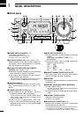
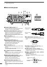
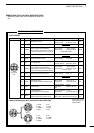
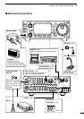

■ Front panel
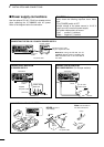
qPOWER SWITCH [POWER] (p. 15)
Turns power ON and OFF.
•Push momentarily to turn power ON.
•Push for 2 sec. to turn power OFF.
w AF GAIN CONTROL [AF] (inner control; p. 15)
Rotate clockwise to increase the audio output from
the speaker; rotate counterclockwise to decrease
the audio output from the speaker.
eRF GAIN CONTROL/SQUELCH CONTROL
[RF/SQL] (outer control; p. 22)
➥Adjusts the squelch threshold level (to mute noise
when receiving no signal) in all modes.
➥This control can be used for RF gain control to
adjust receiver gain manually.
•RF gain selection can be set in initial set mode (p. 50).
•RF gain is usable in SSB/CW/RTTY modes only.
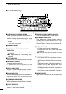
rFUNCTION DISPLAY
Shows the operating frequency, dot matrix indica-
tions, selected memory channel, etc. See p. 7 for
details.
tTUNING STEP SWITCH [TS] (pgs. 17, 18)
➥Push momentarily to cycle between 1 Hz/10 Hz,
programmable and 1 MHz tuning steps.
•1 and 10 Hz steps are only available in SSB, CW and
RTTY modes; 1 MHz steps are only available in FM,
WFM and AM modes.
➥Push for 2 sec. to toggle between 1 and 10 Hz
steps, or; when the programmable tuning steps is
indicated, push for 2 sec. to enter programmable
tuning step mode.
yMODE SWITCH [MODE] (p. 19)
➥Push momentarily to cycle through the operating
modes:
USB/LSB ➧ CW/CWå ➧RTTY/åRTTY ➧
➧ FM/WFM/AM
➥Push and hold for 2 sec. to toggle between the
following operating modes:
USB ↔ LSB
CW ↔ CWå
RTTY↔ åRTTY
FM → WFM → AM → FM, etc.
u
RECEIVE/TRANSMIT INDICATORS [RX]/[TX]
[RX] lights green while receiving (and squelch
opens); [TX] lights red while transmitting.
iMAIN DIAL
Changes the displayed frequency, selects initial set
mode items, etc.
oUP/DOWN (BAND) SWITCHES [Y/Z(BAND)]
➥Push to select a band.
•Can also be used to advance quick set mode items,
initial set mode items, etc.
➥Push and hold to scroll through the bands contin-
uously.
!0MAIN DIAL TENSION LATCH
Selects the main dial tension.
•2 positions are available.
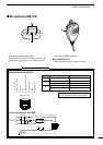
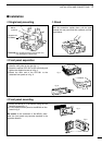
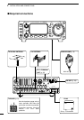
!1MICROPHONE CONNECTOR (p. 8)
Modular-type microphone connector—connects the
supplied microphone (HM-103).
•The optional OPC-589 can be used to connect an 8-pin
microphone such as the SM-8 or SM-20, if desired.
•A microphone connector is also available on the rear
1
1
PANEL DESCRIPTION
HF/VHF/UHF TRANSCEIVER
i706MK™G
AF
RIT/
SUB
MENU F-1 F-2 F-3
MODE
BAND
BAND
Y
Z
TS
DISPLAY
LOCK
RX
TX
M-CH
PHONES
TUNER/CALL
P.AMP/ATT
POWER
SHIFT
RF/SQL
q
w e
r
t
y
i
o
o
!1
!2!3!4!5!6!7!8
!9
@0
@2
@1
!0
u
CH
VFO A
P
O
S1
5
53792040
10
60dB
USB
M1
SPL
A/B A=B