


9
2
INSTALLATION AND CONNECTIONS
■ Unpacking
After unpacking, immediately report any damage to
the delivering carrier or dealer. Keep the shipping car-
tons.
For a description and a diagram of accessory equip-
ment included with the IC-706MKIIG, see UNPACK-
ING on p. ii of this manual.
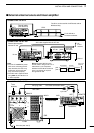
■ Grounding
To prevent electrical shock, television interference
(TVI), broadcast interference (BCI) and other prob-
lems, ground the transceiver through the GROUND
terminal on the rear panel.
For best results, connect a heavy gauge wire or strap
to a long earth-sunk copper rod. Make the distance
between the GROUND terminal and ground as short
as possible.
■ Antenna
Select antenna(s), such as a well-matched 50 Ω
antenna, and feedline. The transmission line should
be a coaxial cable. 1.5 : 1 or better of Voltage
Standing Wave Ratio (VSWR) is recommended for
your required band. Of course, the transmission line
should be a coaxial cable.
CAUTION: Protect your transceiver from lightning
using a lightning arrestor.
RWARNING: NEVER connect the [GND] ter-
minal to a gas or electric pipe, since the connection
could cause an explosion or electric shock.
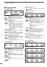
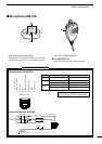
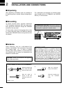
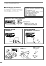
30 mm
10 mm (soft solder)
10 mm
1–2 mm
solder solder
Soft
solder
Coupling ring
PL-259 CONNECTOR INSTALLATION EXAMPLE
➀➂
➃
➁
Slide the coupling ring
down. Strip the cable
jacket and soft solder.
Slide the connector
body on and solder it.
Screw the coupling ring
onto the connector
body.
Strip the cable as
shown at left. Soft
solder the center con-
ductor.
(10 mm ≈
3
⁄8 in)
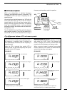
ANTENNA SWR
Each antenna is tuned for a specified frequency
range and SWR may be increased out-of-range.
When the SWR is higher than approx. 2.0: 1, the
transceiver’s power drops to protect the final transis-
tors. In this case, an optional antenna tuner is useful
to match the transceiver and antenna. Low SWR
allows full power for transmitting even when using
the antenna tuner. The IC-706MKIIG has an SWR
meter to monitor the antenna SWR continuously.