


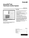

VISIONPRO
®
IAQ TOTAL HOME COMFORT SYSTEM
68-0287—04 8
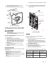
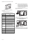
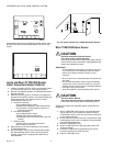
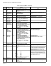
Fig. 18. Typical hookup of fresh air damper.
NOTE: Use this hookup for ventilation using a fresh air
damper.
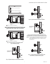
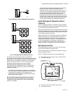
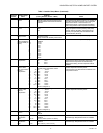
Fig. 19. Typical hookup of powered ventilation.
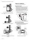
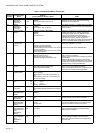
Fig. 20. Hookup of Honeywell DH90 with fresh air intake for
ventilation.
POWER THE THERMOSTAT
• 24 Vac common wire only to EIM or zone panel.
Wiring 24 Vac Common
• Single-Transformer System—Connect the common side of
the transformer to the C screw terminal of the EIM. Leave
the metal jumper wires in place between R, Rc, and RH.
• Two-Transformer System—Connect the common side of
the cooling transformer to the C screw terminal of the EIM.
Remove the metal jumper wire between Rc and Rh.
Connect the hot side of heating transformer to Rh and leave
the jumper wire between R and Rc and connect the hot side
of cooling transformer to R or Rc.
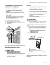
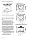
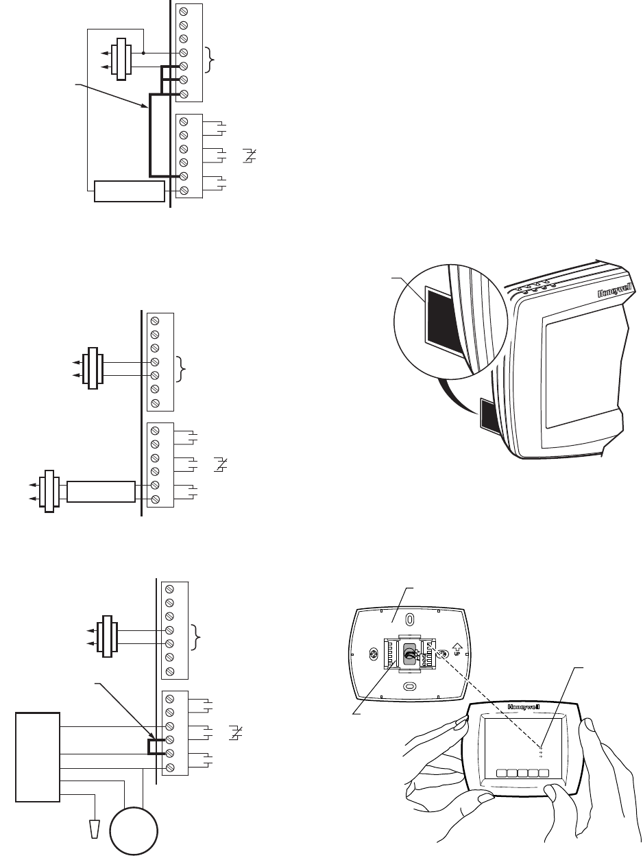
1. Locate and remove the tab labeled, Remove, in the
lower left corner on the thermostat back. See Fig. 21.
Fig. 21. Remove tab labeled, Remove, on thermostat back
Mount Thermostat to Wallplate
1. Align the terminal screw blocks with the pins on the back
of the thermostat. Push the thermostat straight onto the
wallplate until it snaps into place. See Fig. 22.
Fig. 22. Mount thermostat to wallplate.
M23493
FIELD INSTALLED
JUMPER BETWEEN
R AND VNT 1
1
2
3
C
R
RC
RH
24 VAC
H1
U
M2
D1
H
M2
V1
N
T2
OR
NON-POWERED
VENTILATOR
M23494
1
2
3
C
R
RC
RH
24 VAC
H1
U
M2
D1
H
M2
V1
N
T2
OR
POWERED
VENTILATOR
M23495
1
2
3
C
R
RC
RH
24 VAC
H1
U
M2
D1
H
M2
V1
N
T2
OR
FRESH
AIR
DAMPER
DH90
BLUE
GREEN
YELLOW
RED
WHITE
FIELD INSTALLED
JUMPER BETWEEN
DHM 1 AND VNT 1
REMOVE DURING
INSTALLATION
M19920
REMOVE
TAB
REMOVE DURING
INSTALLATION
M23542
PINS ON
BACK OF
THERMOSTAT
WALLPLATE
TERMINAL
SCREW
BLOCK