


VISIONPRO
®
IAQ TOTAL HOME COMFORT SYSTEM
68-0287—04 10
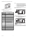
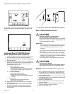
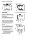
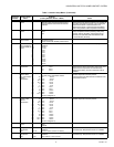
If thermostat is set to Auto Changeover System mode, press
the More key until the outside temperature is shown on the
screen.
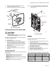
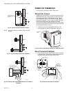
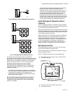
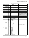
Locate and Mount C7189U1005 Remote
Indoor Temperature Sensor (Optional)
1. Choose a location (see Fig. 25) for mounting the sensor
on an inside wall about 5 ft (1.5m) above the floor.
2. Be sure wire distance between C7189U1005 and EIM is
less than 200 feet.
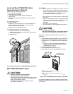
3. Make sure there is good air circulation at average tem-
perature at the chosen location. Avoid the following loca-
tions because they can introduce errors in sensor
measurements. See Fig. 25.
a. Hot areas caused by:
(a)Concealed pipes or ducts.
(b)Drafts from fireplaces or other heat sources.
(c)Convection or radiant heat from the sun or
electrical equipment.
b. Cold areas caused by:
(a)Concealed pipes or ducts.
(b)Drafts from windows and doors.
(c)Unheated areas on the other side of the wall
location.
c. Dead air areas:
(a)Behind doors, furniture and curtains.
(b)In corners and alcoves.
4. Mark the area on the wall selected for mounting the
C7189U1005 Sensor.
5. Run wire cable to a hole at the selected wall location.
Pull approximately three inches of wire through the
opening. Color-coded, 18-gauge thermostat wire is
recommended.
Fig. 25. Typical location for C7189U1005 Indoor Sensor.
Wire C7189U1005 Indoor Sensor
CAUTION
Electrical Interference (Noise) Hazard.
Can cause erratic system operation.
Keep wiring at least one foot away from large inductive
loads such as motors, line starters, lighting ballasts and
large power distribution panels.
IMPORTANT
Erratic temperature readings from a sensor can occur
as a result of any of the wiring practices described
below. Avoid these practices to assure correct
operation.
— Be sure wires have a cable separate from the thermo-
stat cable.
— Do not route temperature sensor wiring with building
power wiring, next to control contactors or near light
dimming circuits, electric motors or welding equipment.
— Avoid poor wiring connections.
— Avoid intermittent or missing building earth ground.
CAUTION
Electrical Shock Hazard.
Can cause electrical shock or equipment damage.
Disconnect power supply before connecting wiring.
Wiring must comply with applicable codes, ordinances and
regulations.
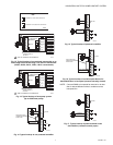
1. Wire C7189U1005 Indoor Sensor to IN1and IN2 termi-
nals on the EIM. For an example of general wiring of
C7189U1005, see Fig. 26 to wire one sensor and Fig. 27
to wire multiple sensors.
2. Push excess wire back into the hole. Plug the hole using
nonhardening caulk, putty or insulation to prevent drafts
from affecting performance.
3. Remove C7189U1005 cover.
4. Mount C7189U1005 to the wall using the screws and
anchors provided.
5. Level the C7189U1005 for appearance only. Device
functions correctly even when not level.
6. Install C7189U1005 cover.
SCHED HOLD CLOCK SCREEN MORE
MON
T
UE
WED
THU
FRI
SA
T
A
A
T
SUN
AM
FAN
A
U
T
O
SYSTEM
HEAT
Following
Schedule
In
s
i
de
Outside
Se
t T
o
M22453
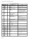
SCHED
SCHED
HOLD
HOLD
CLOCK SCREEN
DONE
WAKE
LEAVE RETURN SLEEP CANCEL
MON
TUE WED THU FRI SAT SUN
Outside
M22448
5 FEET
(1.5 METERS)
YES
NO
NO
NO
M4476