


VISIONPRO
®
IAQ TOTAL HOME COMFORT SYSTEM
35 68-0287—04
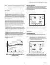
installed with Thermostat Installer Setup Number 340 set to 2,
the temperature displayed on the thermostat home screen as
Inside Temperature will be a 50/50 average between the
temperature sensed at the remote sensor location and the
temperature sensed at the thermostat location.
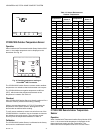
The C7189U1005 Wall Mount Temperature Sensor converts
room temperature to a resistance that the thermostat can
interpret.
The C7189U1005 has a negative temperature coefficient
(NTC), which means that resistance decreases as the
temperature increases. See Table 13.
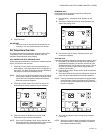
The C7189U1005 can be used to provide one remote sensor
input (see Fig. 26) or as a temperature averaging network with
multiple C7189U1005 Sensors connected, as shown in Fig. 27.
Checkout
For best results, allow C7189U1005 Wall Mount Temperature
Sensor to absorb the air moving through the room for a
minimum of twenty minutes before taking a resistance
measurement.
With an accurate thermometer (±1°F [0.5°C]) measure the
temperature at the sensor location, allowing time for the
thermometer to stabilize before reading.
To verify sensor resistance, remove one wire from one of
C7189U1005 wiring terminals. Use an ohmmeter to measure
the resistance across the sensor. Then verify the sensor
accuracy with the temperature/resistance in Table 13.
Calibration
The C7189U1005 Wall Mount Temperature Sensor is
calibrated at the factory and cannot be recalibrated in the field.
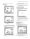
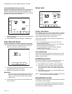
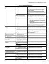
COMMUNICATION ERROR CODES
VisionPRO
®
IAQ can alert the homeowner and installer to
problems with the HVAC equipment, thermostat, or equipment
interface module by using error codes. Please see Table 14 for
a list of error codes. When an error is active (the condition
causing the error is still present) it will be displayed in the time
field on the thermostat home screen. The home screen can
display up to 5 active errors. The time field will flash the time,
“Err,” and a list of up to 5 error codes, beginning with the most
critical, and repeat until the errors have been remedied.
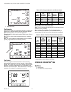
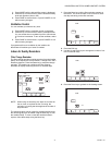
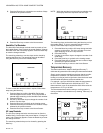
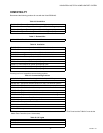
A log of error codes can be viewed at the end of the installer
setup after the system tests. Active errors will be shown first.
The Error Log will log the last ten errors (active and inactive).
Pressing the reset button will clear all inactive errors from the
error log; active errors can not be cleared until the condition
has been remedied.
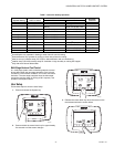
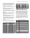
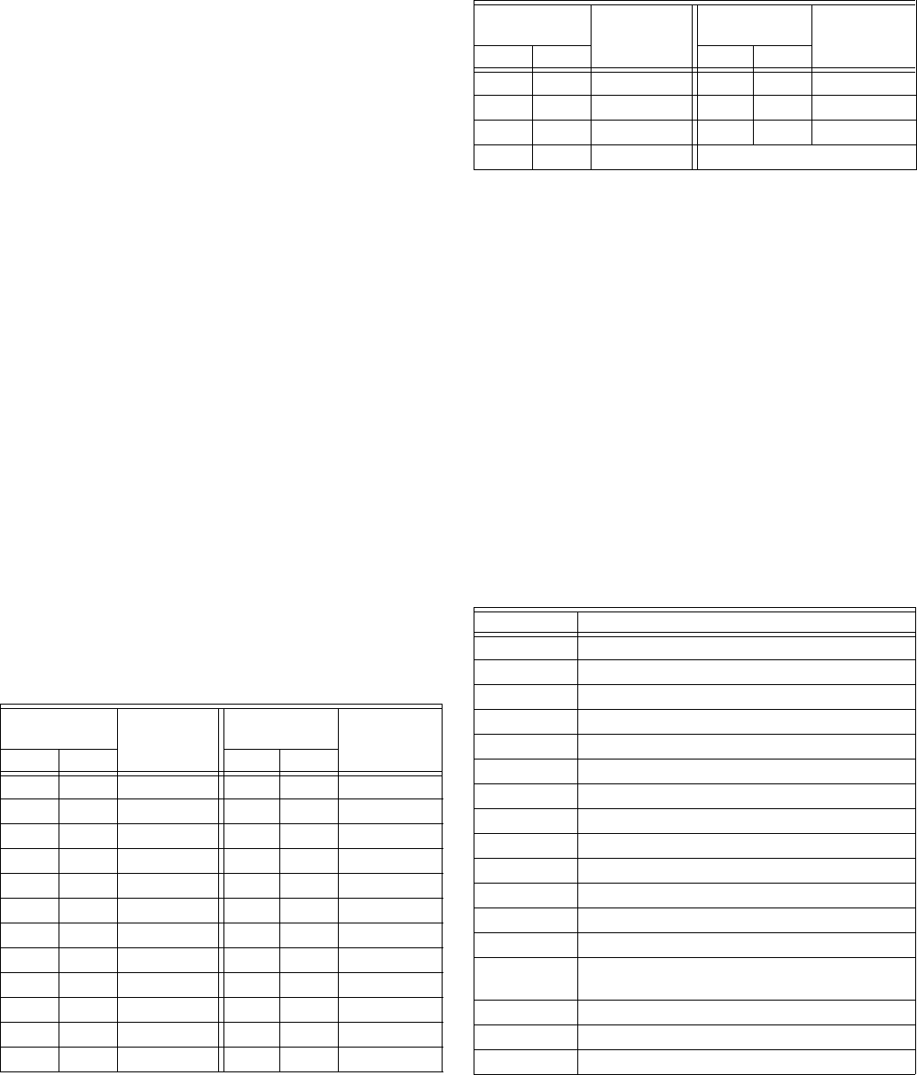
Table 13. Sensor Resistance at Room Temperature.
Room
Temperature
Ohms of
Resistance
Room
Temperature
Ohms of
Resistance°F °C °F °C
40 4.4 22537 72 22.2 11100
42 5.6 21516 74 23.3 10644
44 6.7 20546 76 24.4 10210
46 7.8 19626 78 25.6 9795
48 8.9 18754 80 26.7 9398
50 10.0 17926 82 27.8 9020
52 11.1 17136 84 28.9 8659
54 12.2 16387 86 30.0 8315
56 13.3 15675 88 31.1 7986
58 14.4 14999 90 32.2 7672
60 15.6 14356 92 33.3 7372
62 16.7 13743 94 34.4 7086
64 17.8 13161 96 35.6 6813
66 18.9 12607 98 36.7 6551
68 20.0 12081 100 37.8 6301
70 21.1 11578 —
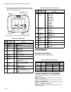
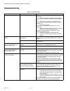
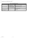
Table 14. VisionPRO
®
IAQ Error Codes.
Error Code Meaning
027 Faulty thermostat (must be replaced)
035 Duplicate thermostat zone detected
036 Duplicate UV timer
037 Duplicate filter timer
038 Duplicate humidifier pad timer
039 Duplicate indoor humidity sensor
040 Compressor should be running but it is not
050 Duplicate outdoor temperature sensor
052 Faulty post-coil air discharge sensor
053 Faulty outdoor temperature sensor
054 Faulty indoor humidity sensor
089 Heating/cooling equipment is missing
090 Data interface is continuously busy
091 Thermostat is not receiving data from other
equipment
118 Faulty discharge air temperature sensor
119 Faulty temperature sensor
121 Duplicate post-coil air discharge sensor
Table 13. Sensor Resistance at Room Temperature.
Room
Temperature
Ohms of
Resistance
Room
Temperature
Ohms of
Resistance°F °C °F °C