


VISIONPRO
®
IAQ TOTAL HOME COMFORT SYSTEM
11 68-0287—04
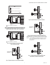
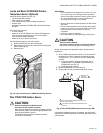
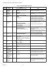
Fig. 26. Wiring a single C7189U1005 Indoor Sensor.
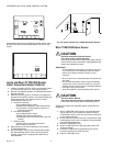
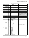
Fig. 27. Wiring Multiple C7189U1005 Sensors.
If a remote indoor temperature sensor is installed, the
thermostat has several options for displaying the current indoor
temperature. This is configured in ISU 340. The thermostat can
display either the temperature measured at the thermostat
location, the sensor location, or a 50-50 average of both.
ONE REMOTE INDOOR SENSOR INSTALLED (OPTIONAL)
If one remote indoor temperature sensor is used, based on
configuration during installer setup, either of the following
options are available:
• The thermostat will display the temperature measured at
the sensor location (internal thermostat sensor is disabled).
• The thermostat will display a 50-50 average of the
temperature measured at the thermostat location and the
remote indoor sensor location.
MULTIPLE REMOTE INDOOR SENSORS INSTALLED (OPTIONAL)
If more than one remote indoor sensor is used, based on
configuration during installer setup, either of the following
options are available:
• The thermostat will display the temperature measured at
the sensor locations (internal thermostat sensor is
disabled). Sensors must be in square numbers (e.g., 4, 9,
16, and so on) and the displayed temperature will be an
average of the temperatures measured at each location.
• The thermostat will display a 50-50 average of the
temperature measured at the thermostat location and the
average of the temperatures measured at the remote indoor
sensor locations. In this case, the thermostat sensor still
carries a 50% weighting of the displayed temperature.
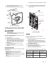
Install Discharge Air Temperature Sensor
(Optional):
Prior to installing Discharge Air Temperature Sensor (DATS)
refer to the installation instructions included with the product for
more information on placement and wiring.
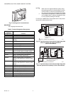
When using a DATS with network zoning the DATS will monitor
the duct air temperature and communicate with the thermostat
and will disable the heating and/or cooling if installer set high or
low temperature limits are reached.
When using a DATS with an Equipment Interface Module the
DATS is for testing only. When the installer is in any of the
Installer Tests pressing the “More” button will display the
temperature measured at the DATS. This allows the installer
to view the temperature of each stage of heating and or
cooling. The DATS will not be used for control and will not
disable heating or cooling based on duct air temperature.
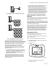
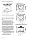
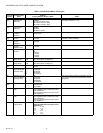
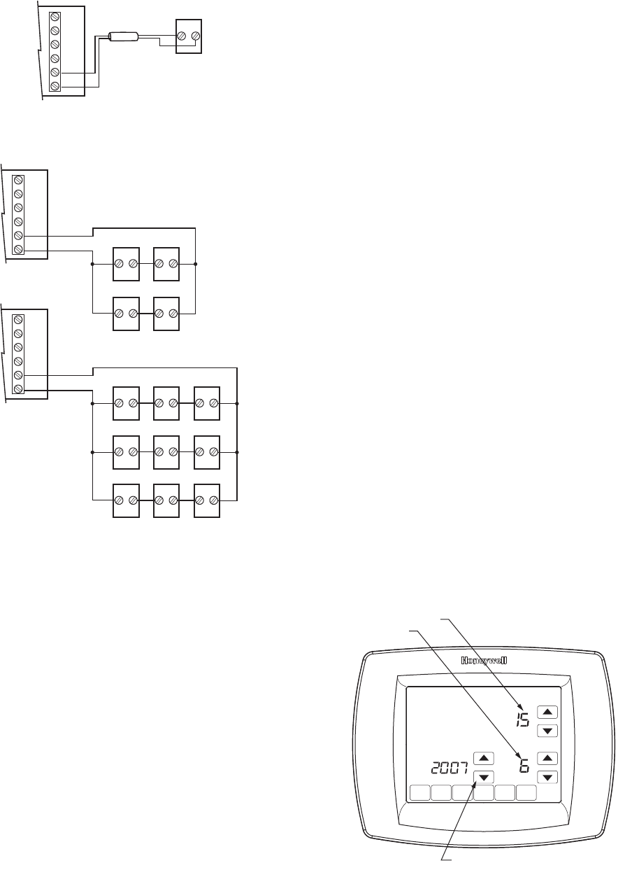
Set Calendar and Time
Thermostat keeps current time and day for up to ten years
under normal use after the calendar is set.
When the thermostat is first powered, the display is ready to
set the calendar and time.
NOTE: Calendar can also be set in the Installer Setup.
1. Press the arrow keys to set the year, month and day.
2. Press the Done key.
3. Press the arrow keys to set the current time.
4. Press the Done Key.
C7189
1 OUT
L
2 IN
1 IN
M23523
2 OUT
M23524
C7189 C7189
C7189 C7189
C7189 C7189
C7189 C7189
C7189
C7189
C7189 C7189 C7189
1 OUT
L
2 IN
1 IN
2 OUT
1 OUT
L
2 IN
1 IN
2 OUT
DONE
MO
MO
WE
WE
TH
TH
FR
FR
S
S
A
A
SU
CHANGE FILTER UV LAMP
OK TO PICK MULTIPLE DAYS SCREEN LOCKED
SET CURRENT DAY
SET MONTH
USE ARROWS TO SET YEAR AND TIME
M22424