


VISIONPRO
®
IAQ TOTAL HOME COMFORT SYSTEM
68-0287—04 24
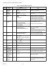
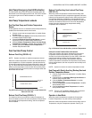
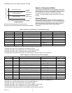
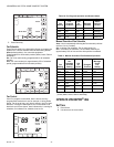
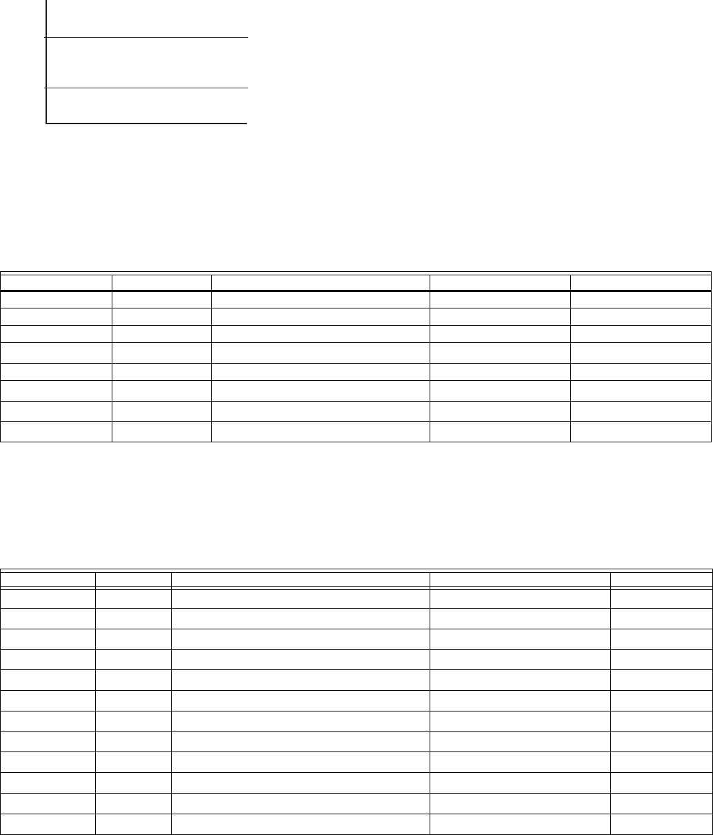
Fig. 32. Heat Pump Operation with Lockout
Temperatures Set.
When the outdoor temperature is between the two
temperatures, both the Compressor and Auxiliary Heat operate.
Operation in Emergency Heat Mode
Once the thermostat is placed into the Emergency Heat mode,
the compressor and auxiliary lockout features are turned off. In
the Emergency heat mode, the compressor is locked out. The
first stage of heat is whatever is connected to the AUX
terminal. The second stage of heat is connected to the AUX2.
terminal.
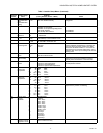
Operating Sequence
The thermostat energizes specific terminal(s), depending on
the demand for heating, cooling or fan. The thermostat screen
shows the time, inside temperature, system and fan selections.
Additional indicators are shown when the heating, cooling or
fan is energized. See Table 5 and 6 for specification
information.
a
G energizes only if Installer set up number 180 is set to Option 1 (Electric Heat).
b
If installer setup (ISU174) is configured for two stages of cooling.
c
If installer setup (ISU 176) is configured for two or more stages of heating.
d
If installer setup (ISU 176) is configured for three stages of heating.
e
G energizes only if Installer set up number 180 is set to Option 1 (Electric Heat) or 2 (Hot water coil).
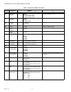
a
Configure O/B in Installer Setup. Based on last piece of equipment called (cooling = O or Heating = B).
b
Red LED is on. See LED indication section for more details (page 22).
c
If installer setup (ISU 174) is configured for 2 compressor stages.
d
If installer setup (ISU 176) is configured for one or more stages of Auxiliary Heat.
e
If installer setup (ISU 176) is configured for two stages of Auxiliary Heat.
f
If thermostat is controlling backup heat, see temperature lockout section (page 23).
35
M19950
COMPRESSOR
LOCKOUT
TEMPERATURE
AUXILIARY
LOCKOUT
TEMPERATURE
COMPRESSOR ONLY
BOTH COMPRESSOR AND
AUXILIARY HEAT
AUXILIARY ONLY
50
OUTDOOR TEMPERATURE
Table 5. Sequence of Operation for Conventional Systems.
System Setting Fan Setting Call for Action Energize Terminals Screen Message
Off Auto None None None
Cool or Auto Auto None None None
Cool or Auto Auto Stage 1 Cooling Y, G Cool On
Cool or Auto Auto Stage 1 and Stage 2 cooling
Y, Y2
b
, G
Cool On
Heat or Auto Auto None None None
Heat or Auto Auto Stage 1 heating
W1, G
a
Heat On
Heat or Auto Auto Stage 1 and Stage 2 heating
W1, W2
c
, G
e
Heat On
Heat or Auto Auto Stage 1, Stage 2 and Stage 3 heating
W1, W2
c
, W3
d
, G
e
Heat On
Table 6. Sequence of Operation for Heat Pump Systems.
System Setting Fan Setting Call for Action Energize Terminals Screen message
Off Auto none
O/B
a
None
Cool or Auto Auto none
O/B
a
None
Cool or Auto Auto Stage 1 cooling
Y, G, O/B
a
Cool On
Cool or Auto Auto Stage 1 and Stage 2 cooling
Y, Y2
c
, G, O/B
a
Cool On
Heat or Auto Auto none
O/B
a
None
Heat or Auto Auto Stage 1 heating
Y, G, O/B
a
Heat On
Heat or Auto Auto Stage 1 and Stage 2 heating
Y, Y2
c
, G, O/B
a
Heat On
Heat or Auto Auto Stage 1, Stage 2 and Stage 3 heating
Y
f
, Y2
c,f
, AUX
d
, G, O/B
a
Aux Heat On
Heat or Auto Auto Stage 1, Stage 2, Stage 3 and Stage 4 heating
Y
f
, Y2
c,f
, AUX
d
, AUX2
e
, G, O/B
a
Aux Heat On
Em.Heat
b
Auto None
O/B
a
None
Em.Heat
b
Auto Stage 1 Heating
AUX
d
, G, O/B
a
Aux Heat On
Em.Heat
b
Auto Stage 1 and Stage 2 heating
AUX
d
, AUX2
e
, G, O/B
a
Aux Heat On