


VISIONPRO
®
IAQ TOTAL HOME COMFORT SYSTEM
5 68-0287—04
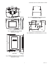
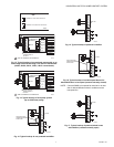
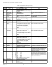
4. Position the wallplate over the holes, pulling wires
through the wiring opening. See Fig. 7.
5. Insert the mounting screws into the holes and tighten.
Fig. 7. Mounting wallplate.
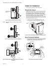
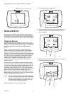
Installing Equipment Interface Module (EIM)
CAUTION
Electrical Hazard.
Can cause electrical shock or equipment damage.
Disconnect power before wiring.
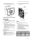
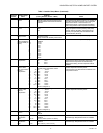
The EIM can be mounted vertically on the HVAC equipment or
on a wall in the equipment room.
1. Position the EIM.
2. Use a pencil to mark the mounting holes.
3. Remove the wallplate from the wall and, if drywall, drill
two 3/16-in. holes in the wall, as marked. For firmer
material such as plaster, drill two 7/32-in. holes. Gently
tap anchors (provided) into the drilled holes until flush
with the wall.
4. Position the wallplate over the holes, pulling wires
through the wiring opening.
5. Insert the mounting screws into the holes and tighten.
See Fig. 8.
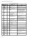
Communication LED
The EIM has an LED (see Fig. 8) that communicates the EIM
status as follows.
• LED blinks rapidly: Normal information transfer.
• LED blinks once: Incoming message to EIM.
• LED blinks continuously: Wiring problem. Check wiring to
terminals 1, 2, 3.
• LED always off: Wiring problem. Check wiring to terminals
1, 2, 3.
• LED always on: EIM may need replacement.
NOTE: It is normal for the LED to blink continuously during
startup, and while checking equipment status (Auto
Discover mode).
Fig. 8. Mounting EIM.
WIRING
All wiring must comply with local electrical codes and
ordinances. See Fig. 10–20.
1. Select set of terminal identifications (Table 1) that corre-
sponds with system type.
2. Loosen the screws for the appropriate system type
selected; see Table 1. See Table 2 for terminal designa-
tion descriptions. Insert wires in the terminal block under
the loosened screw. See Fig. 9.
3. Securely tighten each screw.
4. Push excess wire back into the hole.
5. Plug the hole with nonflammable insulation to prevent
drafts from affecting the thermostat.
6. See Fig. 10–20 for typical wiring hookups.
WALL
MOUNTING
HOLES
M23543
MOUNTING
SCREWS (2)
WALL ANCHORS (2)
WIRES THROUGH WALL
AND WIRE SLOT
M23541
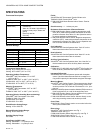
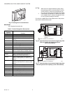
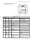
Table 1. Selecting Terminal Identifications for System Type.
System Type
Wallplate Terminal
Identifications
Wiring Diagram
Reference
Standard Heat/Cool Conventional 10, 11
Standard Multistage
up to 3 Heat/2 Cool
Conventional 12
Heat Pump with
Auxiliary Heat
Heat Pump 13
WALL ANCHOR
MOUNTING SCREW
DRILL 3/16 IN. HOLES
FOR DRYWALL. DRILL
7/32 IN. HOLES FOR
PLASTER
COMMUNICATION LED
M23484