


VISIONPRO
®
IAQ TOTAL HOME COMFORT SYSTEM
68-0287—04 6
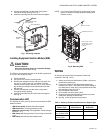
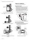
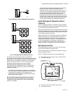
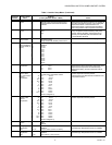
Fig. 9. Inserting wires in terminal block.
IMPORTANT
Use 18-gauge thermostat wire.
NOTES:
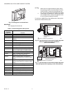
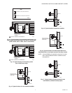
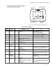
1. When used in a single-transformer system, leave
the metal jumper wires in place between R and Rc,
and Rc and Rh. If used on a two-transformer sys-
tem, remove metal jumper wire between Rc and Rh.
2. If thermostat is configured for a heat pump system
in the Installer Setup, configure changeover valve
for cool (O-factory setting) or heat (B).
For wiring to a W8835 Zone panel please refer to the product
data sheet included with the panel.
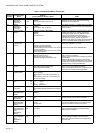
Fig. 10. Typical hookup of conventional single-stage heat
and cool system with single transformer
(1H/1C conventional).
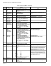
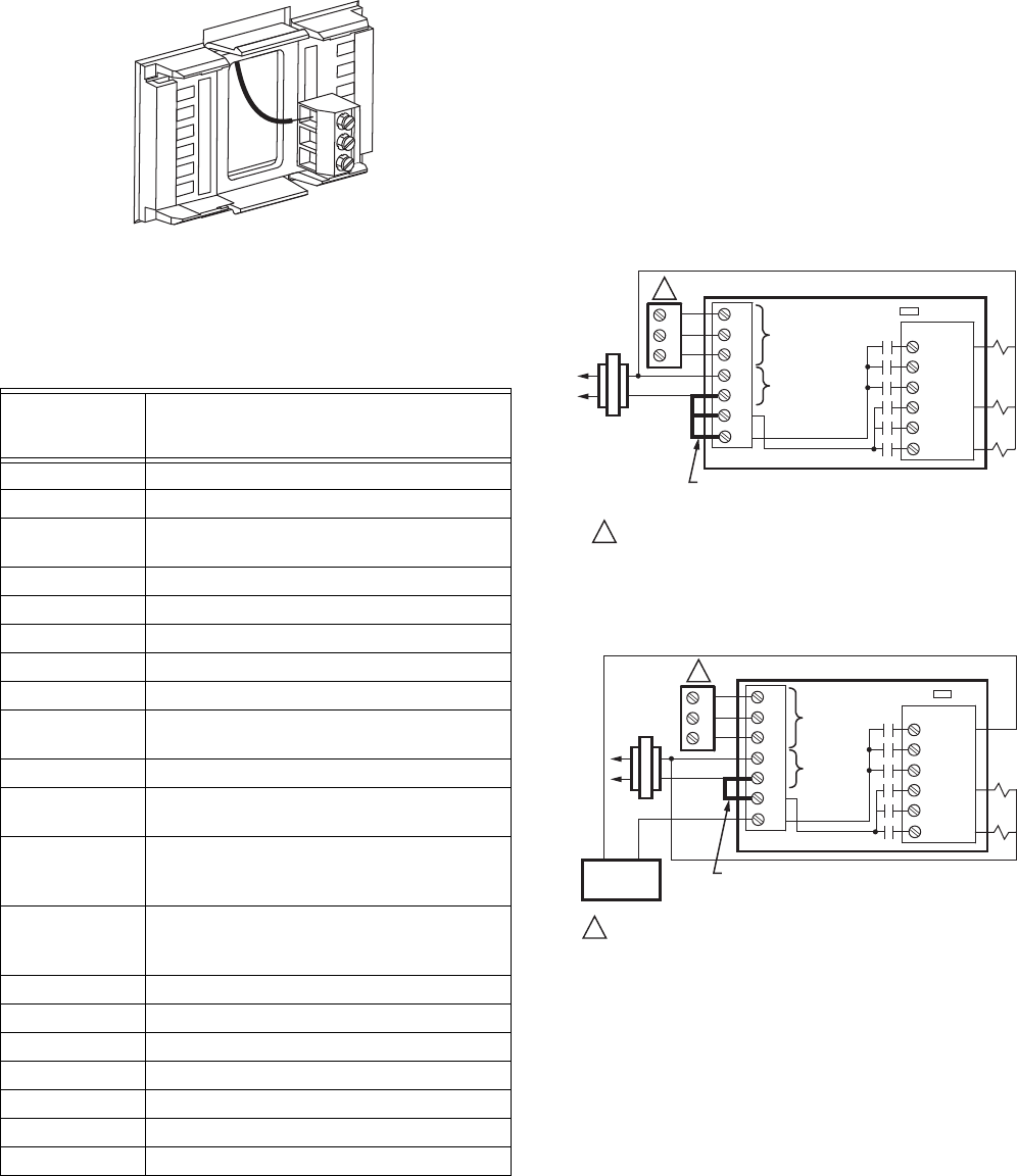
Fig. 11. Typical hookup of conventional single-stage heat
and cool system with oil primary (1H/1C conventional).
Table 2. Terminal Designation Descriptions.
THM5421C1008
Terminal
Designations Function
1 Terminal 1—data to/from thermostat
2 Terminal 2—power from thermostat (24Vac)
3 Terminal 3—common from thermostat
(24Vac)
C 24 Vac Transformer Common
R 24 Vac Transformer
RC 24 Vac Cooling Transformer
RH 24 Vac Heating Transformer
HUM1/HUM2 Humidification Connection (normally open)
DHM1/DHM2 Dehumidification Connection (normally
open or closed based on installer setup)
VNT1/VNT2 Ventilation connection (normally open)
W1/O/B Stage 1 Heating Relay (Conventional)
Change-over Relay (Heat Pump)
W2/AUX Stage 2 Heating Relay (Conventional)
Auxiliary Heat (fossil fuel or electric) (Heat
Pump)
W3/AUX2 Stage 3 Heating Relay (Conventional)
Auxiliary Heat (fossil fuel or electric) (Heat
Pump)
Y Stage 1 Compressor Relay
Y2 Stage 2 Compressor Relay
GFan Relay
L Heat Pump Equipment Monitor
OUT1/OUT2 Outdoor Temperature Sensor
IN1/IN2 Remote Indoor Temperature Sensor
DATS1/DATS2 Discharge Air Temperature Sensor
M23541
M23485
FACTORY INSTALLED
JUMPER BETWEEN R,
RC AND RH
1
2
3
C
R
RC
RH
COMMUNICATION
TERMINALS
COMMUNICATION LED
W1
W2
W3
Y
Y2
G
24 VAC
O/B
AUX
AUX2
Y
Y2
G
1
2
3
WIRE TO TERMINALS ON THERMOSTAT.1
1
CONV. HP
M23486
FACTORY INSTALLED JUMPER BETWEEN R,
AND RC (REMOVE FACTORY INSTALLED
JUMPER BETWEEN RC AND RH
1
2
3
C
R
RC
RH
COMMUNICATION
TERMINALS
COMMUNICATION LED
W1
W2
W3
Y
Y2
G
24 VAC
O/B
AUX
AUX2
Y
Y2
G
1
2
3
OIL PRIMARY/
AQUASTAT
WIRE TO TERMINALS ON THERMOSTAT.1
1
CONV. HP