


59
Hearth & Home Technologies • DV3732SBI, DV3732SBIL • 2215-900 Rev. F • 9/12
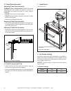
A. RemoveFixedGlassAssembly
See Section 14.G.
B. RemovetheShippingMaterials
Remove shipping materials from inside or underneath the
rebox.
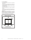
C. CleantheAppliance
Clean/vacuum any sawdust that may have accumulated
inside the rebox or underneath in the control cavity.
D. Accessories
Install approved accessories per instructions included
with accessories. Contact your dealer for a list of ap-
proved accessories.
WARNING! Risk of Fire and Electric Shock! Use ONLY
Hearth & Home Technologies-approved optional acces-
sories with this appliance. Using non-listed accessories
could result in a safety hazard and will void the warranty.
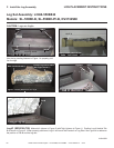
E. LavaRock,Rockwool/EmberPlacement
WARNING! Risk of Explosion! Follow ember placement
instructions in manual. DO NOT place embers directly over
burner ports. Replace ember material annually. Improperly
placed embers interfere with proper burner operation.
PlacingtheLavaRock
See Section 14F for Lava Rock placement instructions.
• Place lava rock on base pan. Do NOT place on burner
top.
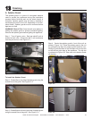
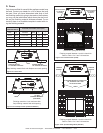
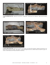
PlacingtheEmberMaterial
Ember material is shipped with this gas appliance. To place
the ember material:
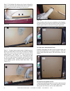
• Embers CANNOT be placed directly over ports. See
Figure 14.4 for the only exception to this guideline. Care
should be taken not to cover the lighting trail of ports
(from back to front).
• When placing Glowing Embers
®
onto the burner care
should be taken so that the ports are not covered. Place
the dime-size ember pieces near the port holes in the
burner top (see Figure 14.3). Failure to follow this pro-
cedure will likely cause lighting and sooting problems.
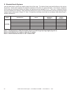
• Some of the small port holes should be covered with
ember material. See Figure 14.4 for detail.
• Save the remaining ember materials for use during
appliance servicing. The embers provided should be
enough for 3 to 5 applications.
Figure14.4PlacementofEmbers
14
ApplianceSetup
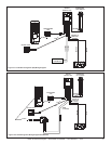
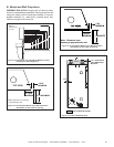
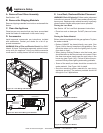
RHEOSTAT
SWITCH
TEMPERATURE
SENSOR
Figure14.1FanWiringwithRheostat
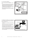
BLUE
VARIABLE
SPEED SWITCH
TEMPERATURE
SENSOR SWITCH
JUNCTION BOX
Figure14.2DetailofFanWiringwithRheostat
PORT HOLES IN CIRCLED AREA
SHOULD BE COVERED WITH EMBER
MATERIAL. NO OTHER PORT HOLES
MAY COME INTO CONTACT WITH
EMBER MATERIAL.
Figure14.3PlacementofEmbers