


6
Model ERCH-HP Energy Recovery Unit
Heat Pump Module
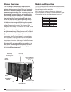
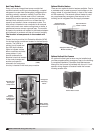
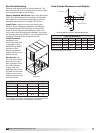
Every unit has an integral heat pump module that
contains hermetic scroll-type compressor(s), a coaxial
refrigerant-to-water heat exchanger(s), refrigerant flow
reversing valve(s), expansion valve(s), liquid line filter
drier, high pressure manual reset cutout, crankcase
heater(s) and various sensors, service ports and safety
devices which allows the unit to run at less than full
capacity and results in fewer compressor cycles. The
heat pump is intended to be connected to an external
water source such as a water cooling tower or boiler, a
geothermal source or even a ground loop. The module
is piped to the airside coil located in the intake airstream
and optionally to a reheat coil that will control humidity.
The location of components in the module will
vary.
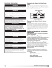
Control circuitry and the Unit Protection Module (UPM)
for the heat pump module are located in the heat pump
module. The UPM is a
printed circuit board and
has LED fault indicator
lights to indicate various
alarm conditions and also
power status. A unit-
specific schematic for
electrical circuits is located
in the control center and
another unit-specific
schematic for heat pump
circuitry is located in the heat pump module.
Unit Protection Module
(UPM)
Refrigerant
Reversing
Valves
Water Intake
and Discharge
Connections
Coaxial
Refrigerant-
to-Water Heat
Exchangers
High Efficiency
Scroll Type
Compressors
Heat Pump Module
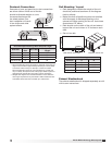
Optional Electric Heaters
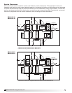
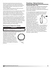
There are two optional electric heaters available. One is
a preheater and is used to prevent frost buildup on the
energy wheel. It is located directly in front of the intake
air filter assembly. The second optional heater is used
as a supplementary emergency heat source for the
building and is integrated into the supply airstream.
Supply Air Motor and
Blower Assembly
Optional Electric
Heater Location
Optional Electric
Preheater Location
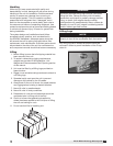
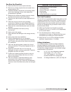
Optional Indirect Gas Furnace
An optional indirect gas furnace may be installed and
provides supplementary emergency heat to the building.
A complete Installation, Operation and Maintenance
Manual for the furnace is provided with the unit. A unit-
specific wiring diagram is located inside the furnace
housing access door.
Indirect Gas Furnace