


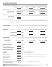

18
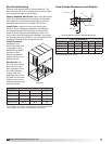
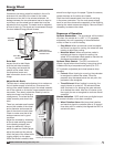
Model ERCH-HP Energy Recovery Unit
1
8
7
5
6
17 16
15
14
13
12
11
10
18
2
3
4
9
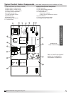
Typical Control Center Components - individual components and locations will vary
Refer to “Heat Pump System”
section for components in
compressor compartment
1. Main disconnect (non-fusible, lockable)
2. Motor starter - exhaust air fan
3. Motor starter - outdoor air fan
4. Motor contactor - energy wheel
5. 24 VAC control transformer
6. 24 VAC terminal strip
7. Fuses for blower motors
8. Grounding lug
9. Distributor block
10. Compressor fuse blocks
11. Terminal block
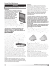
Optional Control Center Components
12. DDC controller
13. Dirty filter pressure switches
14. Economizer module
15. Thermostats for:
- Economizer module
- Energy recovery wheel frost control
16. Terminal block
17. Frost control pressure switch
18. Energy recovery wheel VFD
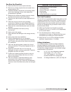
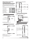
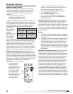
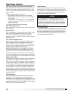
Component #6
Detail of Terminal Strip