


22
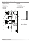
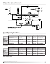
Model ERCH-HP Energy Recovery Unit
Energy Wheel
Start-Up
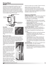
If selected, the energy wheel is installed in the unit’s
airstream with one half of the wheel in the intake
airstream and one half in the exhaust airstream. Air
leakage between the two airstreams has to be kept to
a minimum and the wheel has air seals that must be
adjusted for that purpose. The seals must be adjusted
at time of start-up. The wheel can be accessed through
the door labeled Energy Wheel Access.
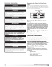
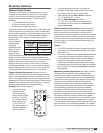
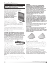
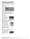
Drive Belt
Inspect the drive belt. Make
sure the belt rides smoothly
in the pulley and around the
outside of the wheel. Note
the directional arrow and
data information shown in the
image.
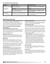
Adjust the Air Seals
The first step in wheel seal adjustment is to make sure
the unit power supply is locked out. Disconnect the
wiring to the wheel module and pull the wheel cassette
out of the cabinet on its tracks. Large cassettes are not
removable. Then slowly rotate the wheel by hand to
make sure there is no binding or
misalignment. The wheel should
rotate smoothly and should not
bind.
There is a perimeter seal located
around the outside of the wheel
and a diameter seal across the
face of the wheel on both sides.
Check to make sure that all air
seals are secure and in good
condition.
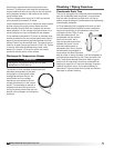
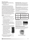
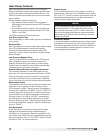
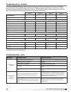
Adjust the air seals by loosening
all the air seal retaining screws
on the bearing support (see
image for reference). Using a
piece of paper as a feeler gauge,
adjust the seals so they almost
touch the face of the wheel while
tugging slightly on the paper.
When the wheel is rotated, there
Motor Pulley and Belt
Sequence of Operation
Optional Economizer - The economizer will be locked
out when: the outside air is <40°F (- 2°F hysteresis,
adjustable); the unit is operating in dehumidification
mode; or there is a call for heating.
• Stop Wheel: When economizer mode is enabled
and there is a signal for cooling, the wheel will stop
rotating to allow free cooling.
• Modulate Wheel: When economizer mode is
enabled and there is a signal for cooling, the
wheel VFD modulates wheel speed to maintain the
discharge temperature set point.
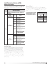
Optional Frost Control - The DDC controller will
output a signal when wheel frosting is occurring which
is determined by a temperature set point (OA <5°F –
2°F hysterisis, adjustable) and wheel pressure drop
increase.
• Preheat: When frosting is occurring, the preheater
is energized to defrost the wheel. Once the
pressure drop decreases below the set point, the
preheater is de-energized.
• Timed Exhaust: When frosting is occurring, the
supply blower is cycled off. The exhaust blower
shall continue to run, allowing the warm exhaust
air to defrost the wheel. After the 10 minute cycle,
the supply fan are re-energized to continue normal
operation.
Alarms Indication - DDC shall have one digital output
for remote indication of an alarm condition.
• Wheel Rotation Alarm: Monitors wheel rotation,
and sends a signal to controller (after a 15 second
time delay with no rotation) that signals the DDC to
activate an alarm.
Bearing Support Bar
showing air seal assembly
Retaining
Screws
should be a slight tug on the paper. Tighten the screws,
repeat the steps on the other set of seals.
Push the wheel cassette back into the unit and plug
in the power connector. Turn the main power supply
back on and then observe the operation of the wheel by
opening the wheel access door slightly. Remove filters if
necessary to observe the wheel.
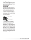
Label showing
cassette serial number
and date code
Bearing Support
Adjustable
Air Seals
Drive Belt
Drive Pulley