


21
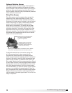
Model ERCH-HP Energy Recovery Unit
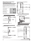
Optional Rotation Sensor
The rotation sensor monitors energy wheel rotation. If
the wheel should stop rotating, the sensor will close a
set of contacts in the unit control center. Field-wiring of
a light (or other alarm) between terminals R and 12 in
the unit control center will notify maintenance personnel
when a failure has occurred.
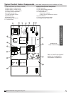
Dirty Filter Sensor
Dirty filter sensors monitor pressure drop across the
outdoor air filters, exhaust air filters, or both. If the
pressure drop across the filters exceeds the set point,
the sensor will close a set of contacts in the unit control
center. Field-wiring of a light (or other alarm) to these
contacts will notify maintenance personnel when
filters need to be replaced. The switch has not been
set at the factory due to external system losses that
will affect the switch. This switch will need minor field
adjustments after the unit has been installed with all
ductwork complete. The dirty filter switch is mounted in
the exhaust inlet compartment next to the unit control
center or in unit control center.
To adjust the switch, the unit must be running with
all of the access doors in place, except for the
compartment where the switch is located (exhaust
intake compartment). The adjusting screw is located on
the top of the switch. Open the filter compartment and
place a sheet of plastic or cardboard over 50% of the
filter media. Replace the filter compartment door. Check
to see if there is power at the alert signal leads. Whether
there is power or not, turn the adjustment screw on the
dirty filter gauge (clockwise if you did not have power,
counterclockwise if you did have power) until the power
comes on or just before the power goes off. Open the
filter compartment and remove the obstructing material.
Replace the door and check to make sure that you do
not have power at the alert signal leads. The unit is now
ready for operation.
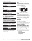
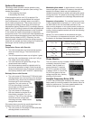
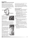
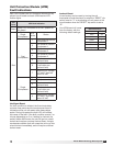
Setscrew (on front of switch) must
be manually adjusted after the
system is in operation.
Negative pressure connection
is toward the ‘front or top’ of
the switch. (senses pressure on
the blower side of filters)
Positive pressure connection is toward the ‘back or bottom’
of the switch. (senses pressure at air inlet side of filters)