


11
Model ERCH-HP Energy Recovery Unit
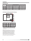
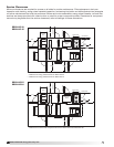
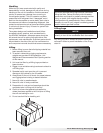
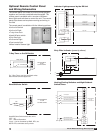
Rail Mounting
Unit Size A B
ERCH-HP 20 5.0 41.0
ERCH-HP 45 7.0 41.9
ERCH-HP 55 5.5 53.0
ERCH-HP 90 6.0 59.0
All dimensions are in inches.
Rail Mounting / Layout
• Rails designed to handle the weight of the unit
should be positioned as shown on the diagram
(rails by others).
• Make sure that rail positioning does not interfere
with the supply air discharge opening or the
exhaust air intake opening on the unit. Avoid area
dimensioned “B” below.
• Rails should run the width of the unit and extend
beyond the unit a minimum of 12 inches on each
side.
• Set unit on rails.
B A
Supply/Exhaust
Outdoor Air
Intake Hood
Opening
Isometric view of unit
B A
Supply/Exhaust
Outdoor Air
Intake Hood
Opening
Side view of unit on rails
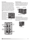
1 Fan
Wheel
Dia.
1 Fan
Wheel
Dia.
R
o
t
a
t
i
o
n
R
o
t
a
t
i
o
n
R
o
t
a
t
i
o
n
R
o
t
a
t
i
o
n
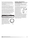
Length of Straight Duct
GOOD
POOR
GOODPOOR
GOOD
POOR
Tu rning
Vanes
Tu rning
Vanes
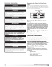
SYSTEM EFFECT FACTOR CURVES
FPM X 100
OUTLET VELOCITY
0 5 10 15 20 25 30 35 40 45
1.2
1.0
0.8
0.6
0.4
0.2
0.0
STATIC PRESSURE LOSS
CURVE 1
CURVE 2
CURVE 3
CURVE 4
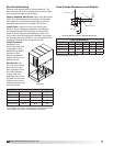
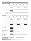
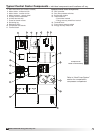
Recommended Discharge Duct Size and Length
Unit Size
Blower
Size
Duct Size
Straight Duct
Length
ERCH-HP 20 9 14 x 14 36
ERCH-HP 45 10 20 x 20 36
ERCH-HP 55 12 20 x 20 36
ERCH-HP 90 15 28 x 28 60
All dimensions shown in inches.
• Recommended duct sizes are based on velocities across the cfm
range of each model at approximately 800 feet per minute (FPM)
at minimum airflow and up to 1600 fpm at maximum airflow.
Recommended duct sizes are only intended to be a guide and
may not satisfy the requirements of the project. Refer to plans for
appropriate job specific duct size and/or velocity limitations.
• Straight duct lengths were calculated based on 100% effective
duct length requirements as prescribed in AMCA Publication 201.
Calculated values have been rounded up to nearest foot.
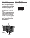
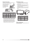
Ductwork Connections
Examples of poor and good fan-to-duct connections
are shown below. Airflow out of the fan
should be directed straight or curve
the same direction as the
fan wheel rotates. Poor
duct installation will result
in low airflow and other
system effects.
1 Fan
Wheel
Dia.
1 Fan
Wheel
Dia.
R
o
t
a
t
i
o
n
R
o
t
a
t
i
o
n
R
o
t
a
t
i
o
n
R
o
t
a
t
i
o
n
Length of Straight Duct
GOOD
POOR
GOODPOOR
GOOD
POOR
Tu rning
Vanes
Tu rning
Vanes
SYSTEM EFFECT FACTOR CURVES
FPM X 100
OUTLET VELOCITY
0 5 10 15 20 25 30 35 40 45
1.2
1.0
0.8
0.6
0.4
0.2
0.0
STATIC PRESSURE LOSS
CURVE 1
CURVE 2
CURVE 3
CURVE 4
Exhaust Weatherhood
The exhaust weatherhood is shipped separately as a kit
with its own instructions.