


15
Model ERCH-HP Energy Recovery Unit
Electrical Information
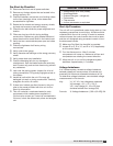
Determine the Size of the Main Power
Lines
The unit’s nameplate states the voltage and the unit’s
MCA. The main power lines to the unit should be sized
accordingly. The nameplate is located on the outside of
the unit on the control panel side.
Determine the Size of Electric Heater
Wiring
An optional electric heater may require a separate
power supply. The power connection should be made
to the factory-provided electric heater disconnect and
must be compatible with the ratings on the nameplate,
supply power voltage, phase and amperage. Consult
ANSI/NFPA 70 and CSA C22.1 for proper conductor
sizing.
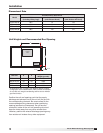
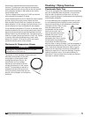
Provide the Opening(s) for the Electrical
Connections
Electrical openings vary by unit size and arrangement
and are field-supplied.
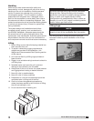
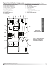
Connect the Power Supplies
Connect the main power lines and electric heater power
lines to the disconnect switches or terminal blocks
and main grounding lug(s). Torque field connections to
manufacturer’s recommendations.
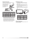
Wire the Optional Convenience Outlet
The convenience outlet requires a separate 115V power
supply circuit. The circuit must include short circuit
protection which may need to be supplied by others.
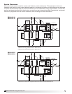
Connect Field-Wired Low Voltage
Components
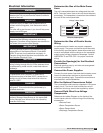
Reference the Ladder Diagram on the inside of the
control center door for correct wiring of the following
accessories:
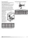
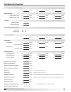
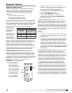
SUP HP
MCA
EXH HP
MOP
VOLTS HZ PH
Unit’s Total MCA
Voltage, Hertz, Phase
SUP HP
MCA
EXH HP
MOP
VOLTS HZ PH
Voltage, Hertz, Phase
Electrical Nameplate
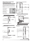
• Remote Panel
• Room Temperature Sensor
• Room Dehumidistat
• Discharge Temperature Sensor
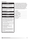
WARNING
The roof lining contains high voltage wiring. To prevent
electrocution, do not puncture the interior or exterior
panels of the roof.
WARNING
To prevent injury or death due to electrocution or
contact with moving parts, lock disconnect switch
open.
For units with a gas furnace, if you turn off the power
supply, turn off the gas.
IMPORTANT
Before connecting power to the unit, read and
understand the following instructions and wiring
diagrams. Complete wiring diagrams are attached on
the inside of the control center door(s).
IMPORTANT
All wiring should be done in accordance with the
latest edition of the National Electric Code ANSI/
NFPA70 and any local codes that may apply. In
Canada, wiring should be done in accordance with
the Canadian Electrical Code.
IMPORTANT
The equipment must be properly grounded. Any
wiring running through the unit in the airstream must
be protected by metal conduit, metal clad cable or
raceways.
CAUTION
If replacement wire is required, it must have a
temperature rating of at least 105ºC, except for an
energy cut-off or sensor lead wire which must be
rated to 150ºC.
DANGER
High voltage electrical input is needed for this
equipment. This work should be performed by a
qualified electrician.
CAUTION
Any wiring deviations may result in personal injury or
property damage. Manufacturer is not responsible
for any damage to or failure of the unit caused by
incorrect final wiring.