


24
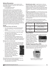
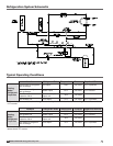
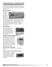
Model ERCH-HP Energy Recovery Unit
Every unit has a complete, sealed refrigeration system
that is ready for connection to a water source.
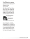
The heat pump has all the typical DX components and
also has refrigerant reversing valve(s) to enable the
system to work in both heating and cooling modes.
Factory-Installed Heat Pump System
Components:
Thermostatic Expansion Valve (TXV)
Each compressor is equipped with a thermal expansion
valve. The valve controls the flow of liquid refrigerant
entering the evaporator coil by maintaining a constant,
factory set superheat of 10ºF.
Refrigerant Distributor
Attached to the TXV is a refrigerant distributor. The
refrigerant distributor evenly distributes the refrigerant
to each circuit of the airside coil to provide optimum
performance.
Airside Coil
Each unit uses a single refrigerant coil known as an
airside coil. If two compressors are used in the unit,
then the airside coil will be a split configuration so that
each compressor has a dedicated portion of the airside
coil. Depending on whether the unit is in cooling or
heating mode, the airside coil will function as either
a condensing coil or an evaporator coil. See also
Subassemblies/Coils.
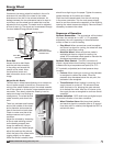
Coaxial Refrigerant-to-Water Heat Exchanger
The unit uses one coaxial heat exchanger per
compressor, essentially a tube inside a tube. Water
flows through the inner copper tube and compressed
refrigerant is forced through the spaces between the
inner and outer tubes. Depending on whether the unit
is functioning in a cooling or a heating capacity, heat is
rejected from one tube to the other.
Liquid Line Filter Drier
The liquid line filter drier prevents moisture and foreign
matter from entering the thermal expansion valve. It is
located in the compressor compartment.
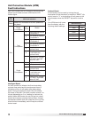
Hot Gas Bypass Valve
On units equipped with hot bypass, hot gas from the
compressor is injected into the liquid line of the airside
coil after the TXV. This process starts when suction gas
temperatures drop below 28ºF, which is 32º–34ºF coil
surface temperature. Hot gas helps the airside coil from
freezing up and the compressor from cycling. The valve
is factory set, but should be field adjusted to maintain a
suction pressure of 90 psi.
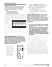
Valve Adjustment: To adjust the valve, connect
a pressure gauge to the suction line and block the
entering air to the coil. The valve should begin to open
when the suction pressure drops to approximately
58 PSIG (the valve will feel warm to the touch).
Adjustments are made by first removing the cap
on the valve and then turning the adjusting stem
counterclockwise to decrease the pressure. Allow
several minutes between adjustments for system to
stabilize. When adjustment is complete, replace the
cap on the valve.
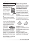
Reversing Valve
Each compressor is equipped with a reversing valve
to reverse the direction of refrigerant flow. The valve is
electrically actuated.
Access Ports
For easy measurement and charging access, several
ports are provided throughout the system. These can be
used to measure system pressures and also charge or
evacuate the system.
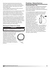
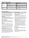
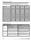
Energy Wheel Troubleshooting
Symptom Possible Cause Corrective Action
Energy wheel
does NOT turn
Air seals are too tight.
See air seals under Start-Up, Energy Wheel
section.
Broken belt. Replace.
No power to wheel motor.
Make sure wheel drive is plugged in. Verify
power is available.
Energy wheel
runs intermittently
Wheel motor overloads are tripping due to
rubbing between wheel and air seals.
Recheck air seals, make sure they are not too
tight. See Adjust the Air Seals under Start-Up,
Energy Wheel section.
Heat Pump Overview