


25
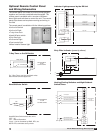
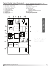
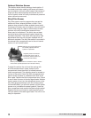
Model ERCH-HP Energy Recovery Unit
Crankcase Heater
A crankcase heater is installed around the base of each
compressor in the unit to boil-off any liquid refrigerant
that may be absorbed into the oil during idle periods. It
is recommended the heater operate 24 hours prior to
the compressors being started.
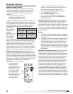
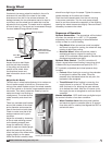
Heat Pump Controls
Each unit is factory provided with a Unit Protection
Module (UPM) that controls compressor operation and
monitors the safety controls that protect the unit. The
UPM is a printed circuit board and is found in the heat
pump module.
Safety controls include the following:
• High pressure switch located in the refrigerant
discharge line and wired across the HPC terminals
on the UPM.
• Low pressure switch located in the unit refrigerant
suction line and wired across terminals LPC1 and
LPC2 on the UPM.
The UPM includes the following features:
Anti-Short Cycle Timer
Five minute delay on break timer to prevent compressor
short cycling.
Random Start
Each controller has a unique random start delay ranging
from 270 to 300 seconds to reduce the chances
of multiple units simultaneously starting after initial
power up or after a power interruption, creating a large
electrical spike.
Low Pressure Bypass Timer
The low pressure switch is bypassed for 120 seconds
after compressor start-up to prevent nuisance low
pressure lockouts during cold start-up in the heating
mode. If the low pressure switch remains opened after
120 seconds, the unit enters a soft lock.
Brownout/Surge/Power Interruption Protection
The brownout protection in the UPM board will shut
down the unit if the incoming power falls below 18VAC.
The unit will remain off until a minimal incoming power
of 18 VAC is detected. Once proper power is restored,
the unit will start-up within the random start time period.
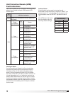
Malfunction Output
The controller has a set of wet contacts for remote fault
indication or dry contacts for communication with a
DDC controller or BMS. The fault output will depend on
the dip switch setting for “ALARM”. If set to “CONST”, a
constant signal will be produced to indicate a fault has
occurred and the unit requires inspection to determine
the type of fault. If it is set to “PULSE”, a pulse signal
is produced and a fault code is detected by a remote
device indicating the fault. The remote device must have
a malfunction detection capability when the UPM board
is set to “PULSE”.
Test Dip Switch
A test dip switch is provided to reduce all time delay
settings to five seconds during troubleshooting or
verification of unit operation. Note that operation of the
unit while in test mode can lead to accelerated wear and
premature failure of the unit. The “TEST” switch must be
set back to “NO” for normal operation.
NOTE
If unit is employing a fresh water system (no anti-
freeze protection), it is extremely important to have
the “Freeze” switch set to 35°F in order to shutdown
the unit at the appropriate leaving water temperature
and protect your heat pump from freezing if a freeze
sensor is included.
Freeze Sensor
This is optional and can be set to ignore or monitor a
freeze sensor. There are two configurable freeze points,
35°F and 15°F. The unit will enter a soft lockout until the
temperature climbs above the set point and the anti-
short cycle time delay has expired.