


16
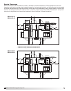
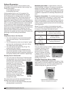
Model ERCH-HP Energy Recovery Unit
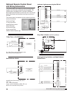
Most factory-supplied electrical components are
prewired. To determine what electrical accessories
require additional field-wiring, refer to the unit-specific
wiring diagram located on the inside of the control
center access door.
The low voltage control circuit is 24 VAC and control
wiring should not exceed 0.75 ohms.
Control wires should not be run inside the same conduit
as that carrying the supply power. Make sure that
field-supplied conduit does not interfere with access
panel operation. All low voltage wiring should be run in
conduit wherever it may be exposed to the weather.
If wire resistance exceeds 0.75 ohms, an insulator relay
should be added to the unit control center and wired in
place of the remote switch (typically between terminal
blocks R and G on the terminal strip. The relay must be
rated for at least 5 amps and have a 24 VAC coil. Failure
to comply with these guidelines may cause motor
starters to “chatter” or not pull in which can cause
contactor failures and/or motor failures.
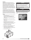
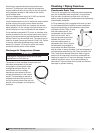
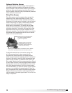
Plumbing / Piping Overview
Condensate Drain Trap
This unit is equipped with a stainless steel condensate
pan with a stainless steel connection. It is important
that the drain connection be fitted with a P trap to
ensure proper drainage of condensate while maintaining
internal static pressures.
A P trap assembly (kit) is supplied with each unit and
is to be assembled and installed as local conditions
require and according to the assembly instructions
provided with the P trap. If local
and area codes permit, the
condensate may be drained
back onto the roof, but a
drip pad should be provided
beneath the outlet. If local
and area codes require a
permanent drain line, it should
be fabricated and installed in
accordance with Best Practices
and all codes. In some climates, it will be necessary to
provide freeze protection for the P trap and drain line.
The P trap should be kept filled with water or glycol
solution at all times and it should be protected from
freezing to protect the P trap from damage. If severe
weather conditions occur, it may be necessary to
fabricate a P trap and drain line of metal and install a
heat tape to prevent freezing.
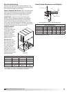
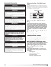
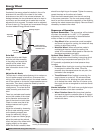
Discharge Air Temperature Sensor
The sensor is to be installed at least three duct
diameters downstream of the heat
exchangers or where good mixed
average temperature occurs. All
other sensor and low voltage
devices are connected to the low
voltage terminal strip in the control
center. This discharge air sensor is
shipped loose and can be found in
the unit’s control center. See the unit-
specific wiring diagram for connection
locations.
WARNING
Discharge air temperature sensor is to be field-
installed prior to unit start-up.