


13
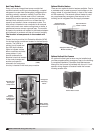
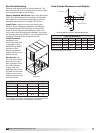
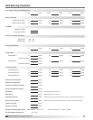
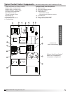
Model ERCH-HP Energy Recovery Unit
Pre-Start-Up Checklist
oDisconnect and lock-out all power switches.
o Remove any foreign objects that are located in the
energy recovery unit.
o Check all fasteners, set-screws, and locking collars
on the fans, bearings, drives, motor bases and
accessories for tightness.
o Rotate the fan wheels and energy recovery wheels
by hand and ensure no parts are rubbing.
o Check the fan belt drives for proper alignment and
tension.
o Filters can load up with dirt during building
construction. Replace any dirty pleated filters and
clean the aluminum mesh filters in the intake hood.
o Verify that non-motorized dampers open and close
properly.
o Check the tightness of all factory wiring
connections.
o Verify control wire gauge.
o Verify diameter seal settings on the energy recovery
wheel.
o Verify proper drain trap installation.
o Check condensing fans for any damage or
misalignment. Spin the blades and make sure they
don’t contact any parts and are free turning without
any resistance.
o Look over the piping system. Inspect for oil at all
tubing connections. Oil typically highlights a leak in
the system.
o Inspect all coils within the unit. Fins may get
damaged in transit or during construction. Carefully
straighten fins with a fin comb.
o If there is an indirect gas-fired furnace in this unit,
refer to the maual provided with this unit for Pre-
Start-Up information.
o This unit contains a crankcase heater for each
compressor which needs power supplied to it
24hours prior to start-up. If start-up is scheduled in
24 hours, unlock the disconnect power and energize
unit.
SPECIAL TOOLS REQUIRED
• Voltage Meter (with wire probes)
• Amperage Meter
• Pressure Gauges – (refrigerant)
• Tachometer
• Thermometer
• Incline manometer or equivalent
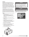
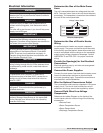
Start-Up Procedure
The unit will be in operational mode during start-up. Use
necessary precautions to avoid injury. All data must be
collected while the unit is running. In order to measure
volts and amps, the control center door must be open,
and the unit energized using a crescent wrench to turn
the disconnect handle.
o Make sure Pre-Start-Up checklist is complete.
o Jumper R to G, R to Y1, and R to Y2 (if applicable)
on the control board.
o Turn the disconnect on. After 3 minutes
compressors will come on. Make sure all fans and
compressors are rotating the correct direction.
o Allow the unit to run until the refrigerant system
stabilizes. Approximately 1-2 minutes.
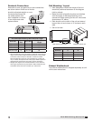
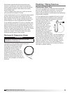
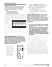
Voltage Imbalance
In a 3-phase system, excessive voltage imbalance
between phases will cause motors to overheat and
eventually fail. Maximum allowable imbalance is 2%.
To determine voltage imbalance, use recorded voltage
measurements in this formula.
Key: V1, V2, V3 = line voltages as measured
VA (average) = (V1 + V2 + V3) / 3
VD = Line voltage (V1, V2 or V3) that
deviates farthest from average (VA)
Formula: % Voltage Imbalance = [100 x (VA-VD)] /VA