


7
IO-247A 12/04
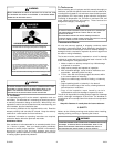
ACCESSIBILITY CLEARANCE,WHERE GREATER, SHOULD
TAKE PRECEDENCE OVER MINIMUM FIRE PROTECTION
CLEARANCE. A gas-fired furnace for installation in a residential
garage must be installed so that the ignition source and burners
are located not less than eighteen inches (18") above the floor and
is protected or located to prevent physical damage by vehicles. A
gas furnace must not be installed directly on carpeting, tile, or
other combustible materials other than wood flooring.
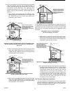
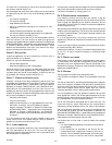
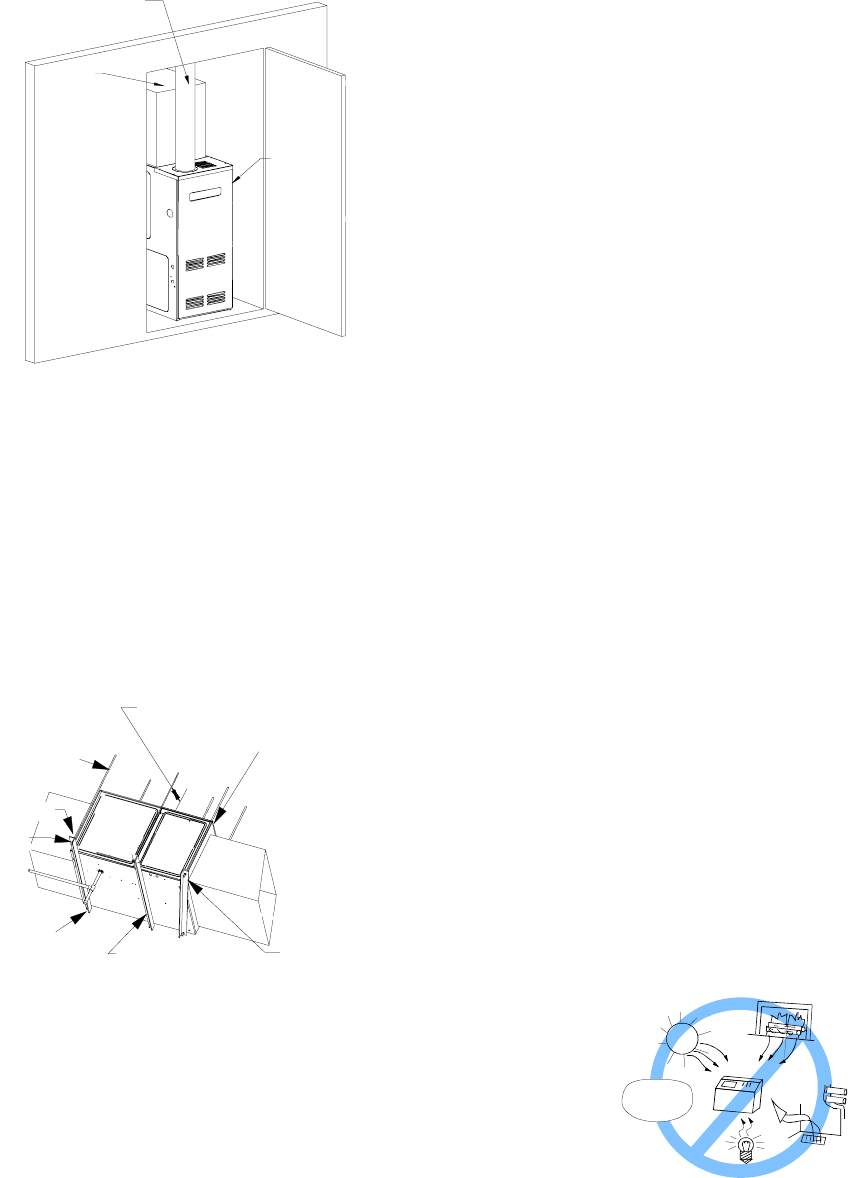
Vent Pipe Clearance to Combustibles -
6" using Single Wall Connector or 1"
using B-1 vent.
Top - 1"
Side
Clearance - 1"
Back - 0"
Front Clearance - 3"
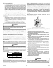
• Adequate combustion/ combustion air must be supplied to
the closet.
• Furnace must be completely sealed to floor or base.
Combustion/ ventilation air supply pipes must terminate 12"
from top of closet and 12" from floor of closet. DO NOT
remove solid base plate for bottom return.
• Return air ducts must be completely sealed to the furnace
and terminate outside the enclosure. surfaces.
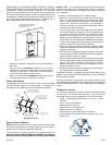
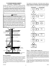
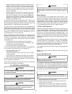
FURNACE SUSPENSION
If suspending the furnace from rafters or joist, use 3/8" threaded
rod and 2”x2”x3/8” angle iron as shown below. The length of rod
will depend on the application and the clearances necessary.
TILT OUTWARD TO ALLOW FOR
DOOR AND CIRCULATOR BLOWER
REMOVAL
3/8" DIAMETER
THREADED ROD
(6 PLACES)
PROVIDE 8" MINMUM CLEARANCE BETWEEN
CENTER ROD AND FURNACE CABINET
TO ALLOW FOR CIRCULATOR BLOWER REMOVAL
ASSURE FURNACE IS LEVEL FROM
END TO END AND HAS A SLIGHT
FORWARD TILT WITH THE FRONT
OF THE FURNACE 0"-3/4"
BELOW THE BACK OF THE FURNACE
POSITION AS CLOSE AS POSSIBLE
TO BLOWER DECK TO ALLOW FOR
CIRCULATOR BLOWER REMVOAL
HOLD DOWN
NUTS
SUPPORT
NUTS
2"x2"x3/8"
ANGLE IRON
(3 PLACES)
Suspended Furnace
EXISTING FURNACE REMOVAL
NOTE: When an existing furnace is removed from a venting system
serving other appliances, the venting system may be too large to
properly vent the remaining attached appliances.
The following vent testing procedure is reproduced from the
American National Standard/National Standard of Canada for
Gas-Fired Central Furnaces ANSI Z21.47b-2002, CSA-2.3b-2002
Section 1.23.1. The following steps shall be followed with each
appliance connected to the venting system placed in operation,
while any other appliances connected to the venting system are
not in operation:
a.Seal any unused openings in the venting system;
b.Inspect the venting system for proper size and horizontal
pitch, as required by the National Fuel Gas Code, ANSI
Z223.1 or the CAN/CSA B149 Installation Codes and these
instructions. Determine that there is no blockage or
restriction, leakage, corrosion and other deficiencies which
could cause an unsafe condition;
c. In so far as practical, close all building doors and windows
and all doors between the space in which the appliance(s)
connected to the venting system are located and other
spaces of the building. Turn on clothes dryers and any
appliance not connected to the venting system. Turn on any
exhaust fans, such as range hoods and bathroom exhausts,
so they shall operate at maximum speed. Do not operate a
summer exhaust fan. Close fireplace dampers;
d.Follow the lighting instructions. Place the appliance being
inspected in operation. Adjust thermostat so appliance shall
operate continuously;
e.Test for draft hood equipped appliance spillage at the draft
hood relief opening after 5 minutes of main burner operation.
Use the flame of a match or candle;
f. After it has been determined that each appliance connected
to the venting system properly vents when tested as outlined
above, return doors, windows, exhaust fans, fireplace
dampers and any other gas burning appliance to their
previous conditions of use;
g.If improper venting is observed during any of the above tests,
the venting system must be corrected.
Corrections must be in accordance with the latest edition of the
National Fuel Gas Code NFPA 54/ANSI Z223.1 and/or CAN/CSA
B149 Installation Codes.
If resizing is required on any portion of the venting system, use the
appropriate table in Appendix G in the latest edition of the National
Fuel Gas Code ANSI Z223.1 and/or CAN/CSA B149 Installation
Codes.
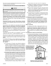
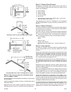
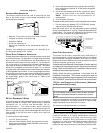
THERMOSTAT LOCATION
In an area having good air circulation, locate the thermostat about
five feet high on a vibration-free inside wall. Do not install the
thermostat where it may be influenced by any of the following:
• Drafts, or dead spots behind doors, in corners, or under
cabinets.
• Hot or cold air from registers.
• Radiant heat from the sun.
• Light fixtures or other appliances.
• Radiant heat from a fireplace.
• Concealed hot or cold water pipes, or chimneys.
• Unconditioned areas behind the thermostat, such as an
outside wall.
HOT
COLD
DRAFTS OR DEAD SPOTS
-BEHIND DOORS
-IN CORNERS
-UNDER CABINETS
Thermostat Influences