


22
IO-247A 12/04
1. Close the manual gas shutoff valve external to the furnace.
2. Turn off the electrical power to the furnace.
3. Set the room thermostat to the lowest possible setting.
4. Remove the burner compartment door.
NOTE: This furnace is equipped with an ignition device which
automatically lights the burner. Do not try to light the burner by
hand.
5. Move the furnace gas valve manual control to the OFF
position.
6. Wait five minutes then smell for gas. Be sure check near
the floor as some types of gas are heavier than air.
7. If you smell gas after five minutes, immediately follow the
instructions on page 5 of this manual. If you do not smell
gas after five minutes, move the furnace gas valve manual
control to the ON position.
8. Replace the burner compartment door.
9. Open the manual gas shutoff valve external to the furnace.
10. Turn on the electrical power to the furnace.
11. Adjust the thermostat to a setting above room temperature.
12. After the burners are lit, set the thermostat to desired
temperature.
NOTE: There is an approximate 30 second delay between
thermostat energizing and burner firing.
FURNACE SHUTDOWN
1. Set the thermostat to lowest setting.
2. Turn off the electrical power supply to the furnace.
3. Remove the burner compartment door and move the furnace
gas valve manual control to the OFF position.
4. Close manual gas shutoff valve external to the furnace.
5. Replace the burner compartment door.
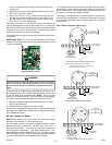
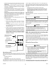
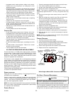
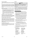
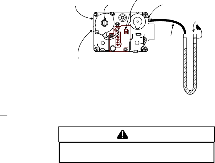
High Manifold
Regulator Adjustment
Screw (Under Cap)
Inlet Pressure Tap
(Side of Valve)
Low Manifold
Regulator Adjustment
Screw (Under Cap)
Outlet (Manifold)
Pressure Tap
(Side of Valve)
Gas Valve
Manual Control
Manometer
Open to
Atmosphere
Manometer
Hose
White-Rodgers Model 36E54 Connected to Manometer
GAS SUPPLY PRESSURE MEASUREMENT
operating.
CAUTION
T
O PREVENT UNRELIABLE OPERATION OR EQUIPMENT DAMAGE, THE INLET
GAS SUPPLY PRESSURE MUST BE AS SPECIFIED ON THE UNIT RATING PLATE
WITH ALL OTHER HOUSEHOLD GAS FIRED APPLIANCES OPERATING.
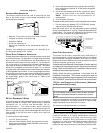
The line pressure supplied to the gas valve must be within the
range specified below. The supply pressure can be measured at
the gas valve inlet pressure tap or at a hose fitting installed in the
• Integrated control module performs safety circuit checks.
• Outdoor fan and compressor are energized to their
appropriate speed.
• Circulator blower is energized on the appropriate cool speed
following a fixed five second on delay. The circulator blower
requires 30 seconds to ramp up to full speed. Electronic air
cleaner terminals are energized with circulator blower.
• Furnace circulator blower and outdoor cooling unit run their
appropriate speed, integrated control module monitors
safety circuits continuously.
• R and YLO/G or Y/G thermostat contacts open, completing
the call for cool.
• Outdoor fan and compressor are de-energized.
• Circulator blower continues running for a cool off delay
period. The OFF delay time and airflow level are determined
by the selected ramping profile.
• Electronic air cleaner terminals and circulator blower are
de-energized.
• Furnace awaits next call from thermostat.
CONSTANT FAN
• R and G thermostat contacts close, initiating a call for fan.
• Integrated control module performs safety circuit checks.
• Circulator blower is energized on continuous fan speed (56%
of high stage cooling) following a five (5) second delay.
Electronic air cleaner terminals are energized.
• Circulator blower runs, integrated control module monitors
safety circuits continuously.
• R and G thermostat contacts open, completing the call for
fan.
• Circulator blower is de-energized. Electronic air cleaner
terminals are de-energized.
• Furnace awaits next call from thermostat.
XII. START-UP PROCEDURE AND ADJUSTMENT
Furnace must have a 115 VAC power supply properly connected
and grounded. Proper polarity must be maintained for correct
operation. An interlock switch prevents furnace operation if the
blower door is not in place. Keep the blower access door in place
except for inspection and maintenance.
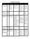
This furnace is also equipped with a self-diagnosing electronic
control module. In the event a furnace component is not operating
properly, the control module LED will flash on and off in a factory-
programmed sequence, depending on the problem encountered.
This light can be viewed through the observation window in the
blower access door. Refer to the Troubleshooting Chart for further
explanation of the lighting codes.
Follow the start-up and adjustment items, refer to further information
in Section XIII, Operational Checks.
FURNACE OPERATION
Purge gas lines of air prior to start-up. Do not purge lines into an
enclosed burner compartment.
Check for leaks using an approved chloride-free soap and water
solution, an electronic combustible gas detector, or other approved
method. Verify that all required kits (propane gas, high altitude,
etc.) have been appropriately installed.
NOTE: An interlock switch prevents furnace operation if the blower
door is not in place. Keep the blower access doors in place except
for inspection and maintenance.
FURNACE START-UP