


24
IO-247A 12/04
5. Turn ON gas and relight appliances turned off in step 1.
Ensure all the appliances are functioning properly and that
all pilot burners are operating.
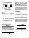
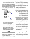
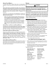
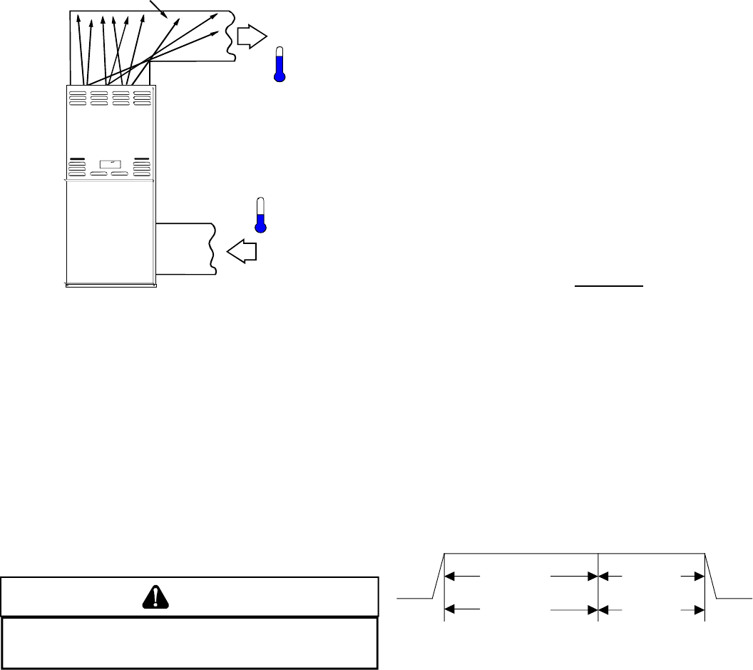
TEMPERATURE RISE
Air temperature rise is the temperature difference between supply
and return air. The proper amount of temperature rise is usually
obtained when the unit is operated at the rated input with the “as
shipped” blower speed. If the correct amount of temperature rise
is not obtained, it may be necessary to change the blower speed.
An incorrect temperature rise can cause condensing in or
overheating of the heat exchanger. Determine and adjust the
temperature rise as follows. The temperature rise must be within
the range specified on the rating plate or Product Data Book
applicable to your model*.
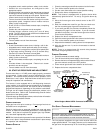
RISE =
SUPPLY
AIR
RETURN
AIR
HEAT EXCHANGER
RADIATION "LINE OF SIGHT"
T
RETURN
T
SUPPLY
T
SUPPLY
-
T
RETURN
Temperature Rise Measurement
1. Operate furnace with burners firing approximately 15
minutes. Ensure all registers are open and all duct dampers
are in their final (fully or partially open) position.
2. Place thermometers in the return and supply ducts as close
to the furnace as possible. Thermometers must not be
influenced by radiant heat by being able to “see” the heat
exchanger.
3. Subtract the return air temperature from the supply air
temperature to determine the air temperature rise. Allow
adequate time for thermometer readings to stabilize.
4. Adjust temperature rise by adjusting the circulator blower
speed. Increase blower speed to reduce temperature rise.
Decrease blower speed to increase temperature rise. Refer
to the following section for speed changing details.
CIRCULATOR BLOWER SPEED ADJUSTMENT
WARNING
T
O AVOID PERSONAL INJURY OR DEATH DUE TO ELECTRICAL SHOCK, TURN
OFF
POWER TO THE FURNACE BEFORE CHANGING SPEED TAPS.
All furnaces are shipped with heating speed set at “B” and cooling
speed set at “D”. Use the following procedure to select the heating
and cooling speed needed for your unit.
Use the CFM LED (green), adjacent to the integrated control
module fuse to verify airflow quantity. The green CFM LED
blinks once for each 100 CFM of airflow.
1. Determine the tonnage of the cooling system installed with
the furnace. If the cooling capacity is in BTU/hr divide it by
12,000 to convert capacity to TONs.
Example: Cooling Capacity of 30,000 BTU/hr.
30,000/12,000 = 2.5 Tons
2. Determine the proper air flow for the cooling system. Most
cooling systems are designed to work with air flows between
350 and 450 CFM per ton. Most manufacturers recommend
an air flow of about 400 CFM per ton.
Example: 2.5 tons X 400 CFM per ton = 1000 CFM
The cooling system manufacturer’s instructions must be checked
for required air flow. Any electronic air cleaners or other devices
may require specific air flows, consult installation instructions of
those devices for requirements.
3. Knowing the furnace model, locate the high stage cooling
air flow charts in the Product Data Book applicable to your
model* . Look up the cooling air flow determined in step 2
and find the required cooling speed and adjustment setting.
Example: A 70 kBtu furnace is to be installed with a 2.5
ton air conditioning system. The air flow
needed is 1000 CFM. Using the cooling speed
chart for the 70 kBtu furnace, find the airflow
closest to 1000 CFM. A cooling airflow of 990
CFM can be attained by setting the cooling
speed to “C” and the adjustment to “-” (minus).
NOTE: Continuous Fan Speed will be 56% of
high stage cooling.
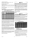
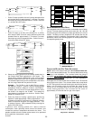
4. Locate the blower speed selection DIP switches on the
integrated control module. Select the desired “cooling”
speed tap by positioning switches 1 and 2 appropriately.
Select the desired “adjust” tap by positioning switches 3
and 4 appropriately. Refer to the following figure for switch
positions and their corresponding taps. Turn off power to
furnace for a minimum of
10 seconds, allowing motor to
reset and recognize new speed selection. Turn on power
to furnace. Verify CFM by counting the number of times the
green CFM LED blinks.
5. The multi-speed circulator blower also offers several custom
ON/OFF ramping profiles. These ramping profiles may be
used to enhance cooling performance and increase comfort
level. The ramping profiles are selected using DIP switches
5 and 6. Refer to the following figure for switch positions
and their corresponding taps. Refer to the bullet points below
for a description of each ramping profile. Turn off power to
furnace for a minimum of 10 seconds, allowing motor to
reset and recognize the new profile selection. Turn on power
to the furnace. Verify profile selection by counting the green
CFM LED blinks and timing each step of the ramping profile
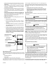
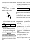
• Profile A provides only an OFF delay of 1 minute at 100% of
the cooling demand airflow.
100% CFM
1 min
100% CFM
Cooling
Demand
OFF OFF
• Profile B ramps up to full cooling demand airflow by first
stepping up to 50% of the full demand for 30 seconds. The
motor then ramps to 100% of the required airflow. A 1 minute
OFF delay at 100% of the cooling airflow.