18
IO-247A 12/04
1,000 Btu/ft
3
is determined by-
Corrected Input = 90,000 - (6,000 X .04) X (90,000 / 1,000)
Corrected Input = 90,000 - (240 X 90)
Corrected Input = 90,000 - 21,600
Corrected Input = 68,400
Using the orifices sized as shown in the table for 6,000 feet (#45),
a meter time of 52.6 seconds is measured. The actual firing rate
of the furnace is
Input = 1,000 (heating value of the gas) X 3600 (constant) / 52.6
(meter time for 1 ft
3
of gas)
Input = 3,600,000 / 52.6
Input = 68,400 Btu/h
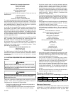
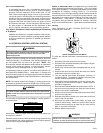
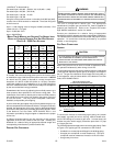
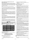
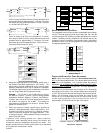
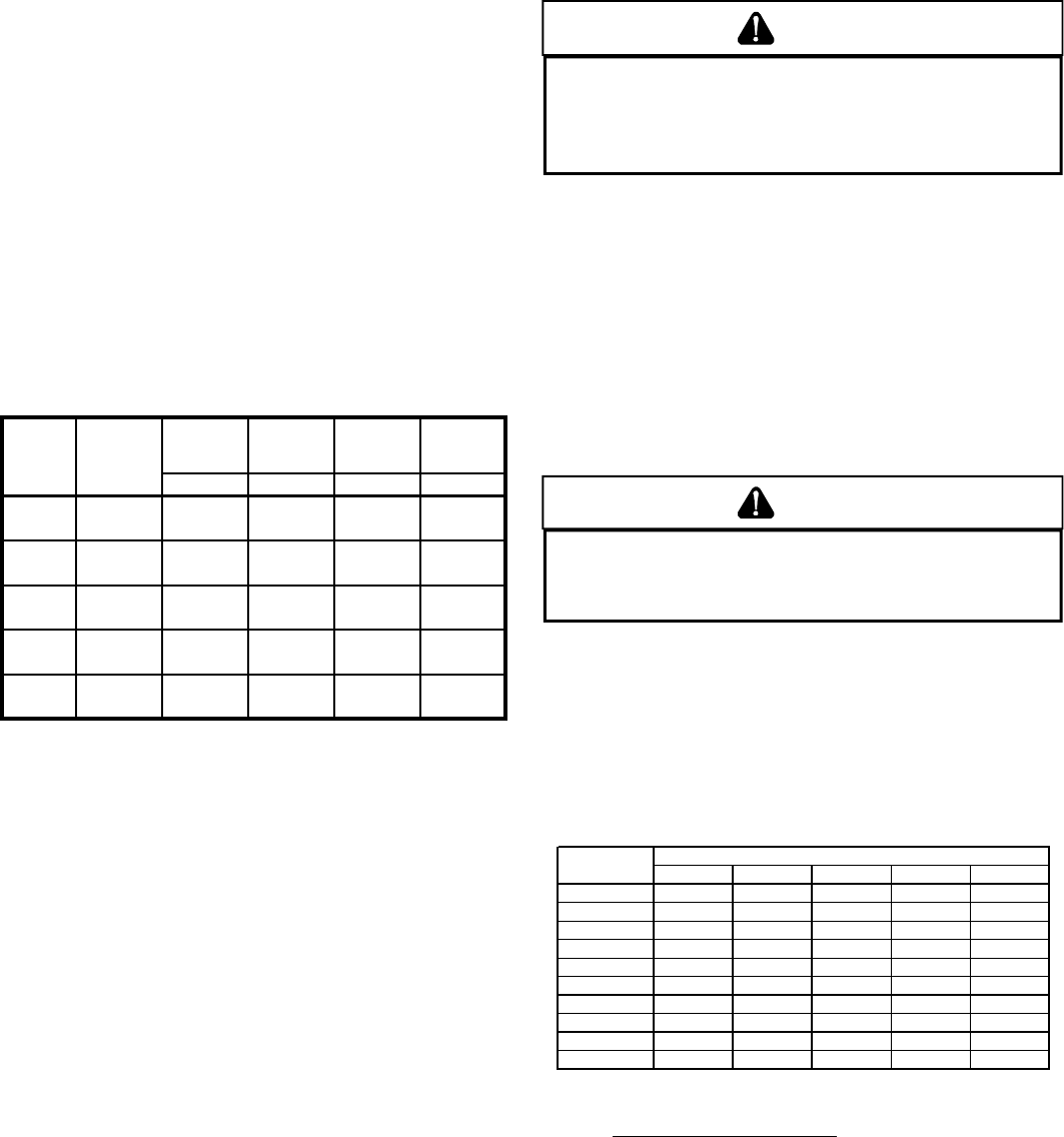
METER TIME IN MINUTES AND SECONDS FOR NORMAL INPUT
RATING OF FURNACES EQUIPPED FOR USE WITH NATURAL
GAS AT 0 - 2,000 FEET ALTITUDE
INPUT METER
IZE
HEAT
VAL
E
HEAT
VAL
E
HEAT
VAL
E
HEAT
VAL
E
Btu/hr
FT
3
900 1,000 1040 1,100
MIN. SEC. MIN.SEC MIN. SEC. MIN. SEC.
1 1 21 1 30 1 33 1 39
10 13 30 15 00 15 36 16 30
1 0 54 1 00 1 03 1 06
10 9 00 10 10 10 24 11 00
1 0 41 0 45 0 47 0 50
10 6 45 7 30 7 48 8 15
1 0 32 0 36 0 37 0 40
10 5 24 6 00 6 14 6 36
1 0 27 0 30 0 31 0 33
10 4 30 5 00 5 12 5 30
120,000
40,000
60,000
80,000
100,000
In Canada, the series and rating plate input for the furnace apply
to installations up to 2,000 feet (610m) above sea level. Kit HA-02
for natural and LP gases is required to convert furnaces from
elevations of 2,000 to 4,500 feet (610m to 1,370m). Canadian
certification applies to the installations of up to 4,500 feet above
sea level. Installations above 4,500 feet are subject to acceptance
by the local authorities having jurisdiction.
Do not derate the furnace by adjusting the manifold pressure to a
lower pressure than specified on the furnace rating plate. The
combination of the lower air density and a lower manifold pressure
will prohibit the burner orifice from drawing the proper amount of
air into the burner. This may cause incomplete combustion,
flashback, and possible yellow tipping.
In some areas the gas supplier may artificially derate the gas in an
effort to compensate for the effects of altitude. If the gas is artificially
derated, the appropriate orifice size must be determined based
upon the BTU/ft
3
content of the derated gas and the altitude. Refer
to the National Fuel Gas Code, NFPA 54/ANSI Z223.1, and
information provided by the gas supplier to determine the proper
orifice size.
A different pressure switch may be required at high altitude
regardless of the BTU/ft
3
content of the fuel used. Contact your
distributor for a tabular listing of appropriate altitude ranges and
corresponding manufacturer’s pressure switch kits.
PROPANE GAS CONVERSION
WARNING
P
OSSIBLE PROPERTY DAMAGE, PERSONAL INJURY OR DEATH MAY OCCUR IF
THE CORRECT CONVERSION KITS ARE NOT INSTALLED.
T
HE APPROPRIATE KITS
MUST BE APPLIED TO INSURE SAFE AND PROPER FURNACE OPERATION.
A
LL
CONVERSIONS MUST BE PERFORMED BY A QUALIFIED INSTALLER OR SERVICE
AGENCY.
This unit is configured for natural gas. The appropriate
manufacturer’s propane gas conversion kit, must be applied for
propane gas installations. Refer to the “Propane Gas and/or
High Altitude Installations” section for details.
Contact your distributor for a tabular listing of appropriate
manufacturer’s kits for propane gas and/or high altitude installations.
The indicated kits must be used to insure safe and proper furnace
operation. All conversions must be performed by a qualified
installer, or service agency.
GAS PIPING CONNECTIONS
GENERAL
CAUTION
TO AVOID POSSIBLE UNSATISFACTORY OPERATION OR EQUIPMENT DAMAGE
DUE TO UNDERFIRING OF EQUIPMENT, USE THE PROPER SIZE OF
NATURAL/PROPANE GAS PIPING NEEDED WHEN RUNNING PIPE FROM THE
METER/TANK TO THE FURNACE.
When sizing a trunk line, be sure to include all appliances which
will operate simultaneously when sizing a trunk line.
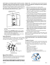
The gas piping supplying the furnace must be properly sized based
on the gas flow required, specific gravity of the gas, and length of
the run. The gas line installation must comply with local codes, or
in their absence, with the latest edition of the National Fuel Gas
Code, NFPA 54/ANSI Z223.1.
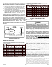
Natural Gas Capacity of Pipe
In Cubic Feet of Gas Per Hour (CFH)
Length of Nominal Black Pipe Size
Pipe in Feet 1/2" 3/4" 1" 1 1/4" 1 1/2"
10 132 278 520 1050 1600
20 92 190 350 730 1100
30 73 152 285 590 980
40 63 130 245 500 760
50 56 115 215 440 670
60 50 105 195 400 610
70 46 96 180 370 560
80 43 90 170 350 530
90 40 84 160 320 490
100 38 79 150 305 460
(Pressure 0.5 psig or less and pressure drop of 0.3" W.C.; Based on
0.60 Specific Gravity Gas)
CFH =
BTUH Furnace Input
Heating Value of Gas (BTU/Cubic Foot)
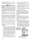
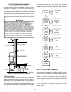
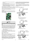
To connect the furnace to the building’s gas piping, the installer
must supply a ground joint union, drip leg, manual shutoff valve,
and line and fittings to connect to gas valve. In some cases, the
installer may also need to supply a transition piece from 1/2" pipe
to a larger pipe size.
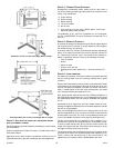
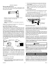
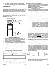
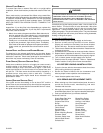
The following stipulations apply when connecting gas piping. Refer
to Figure 16 for typical gas line connections to the furnace.
• Use black iron or steel pipe and fittings for the building piping.
• Use pipe joint compound on male threads only. Pipe joint
compound must be resistant to the action of the fuel used.
• Use ground joint unions.