


21
IO-247A 12/04
FILTERS - READ THIS SECTION BEFORE INSTALLING THE
RETURN AIR DUCTWORK
Filters must be used with this furnace. Discuss filter maintenance
with the building owner. Filters do not ship with this furnace, but
must be provided by the installer. Filters must comply with UL900
or CAN/ULCS111 standards. If the furnace is installed without filters,
the warranty will be voided.
NOTE: An undersized opening will cause reduced airflow.
For air delivery of less than 1800 CFM, use a one side or bottom
return. For air delivery of 1800 CFM or higher, use either two-
sided returns or a one-sided return with a bottom return. Refer to
Minimum Filter Area tables at the end of this manual to determine
filter area requirements.
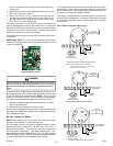
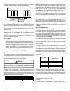
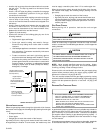
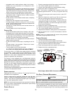
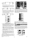
UPRIGHT I NSTALLATIONS
Depending on the installation and/or customer preference,
differing filter arrangements can be applied. Filters can be
installed in the central return register or a side panel external filter
rack kit (upflows), or the ductwork above a counterflow furnace. As
an alternative, a media air filter or electronic air cleaner can be
used as the requested filter. The following figures show possible
filter locations.
CIRCULATION A IR F ILTERS
One of the most common causes of a problem in a forced air heating
system is a blocked or dirty filter. Circulating air filters must be
inspected monthly for dirt accumulation and replaced if necessary.
Failure to maintain clean filters can cause premature heat
exchanger failure.
A new home may require more frequent replacement until all
construction dust and dirt is removed. Circulating air filters are to
be installed in the return air duct external to the furnace cabinet.
WARNING
B
EFORE PERFORMING ANY SERVICE ON THIS FURANCE, DISCONNECT THE
MAIN POWER SUPPLY.
D
O NOT OPERATE THE FURNACE WITHOUT
CIRCULATIONG AIR FILTERS IN PLACE.
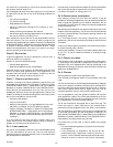
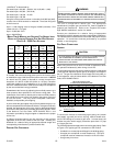
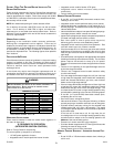
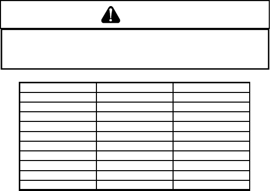
FURNACE INPUT FILTER SIZE TYPE
45M
160 in
2
permanent
68M
241 in
2
permanent
90M
320 in
2
permanent
115M
400 in
2
permanent
135M
370 in
2
permanent
45M
320 in
2
disposable
68M
483 in
2
disposable
90M
640 in
2
disposable
115M
800 in
2
disposable
135M
738 in
2
disposable
PERMANENT NOMINAL 600 F.P.M.
DISPOSABLE NOMINAL 300 F.P.M.
MINIMUM FILTER SIZES
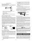
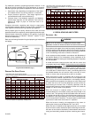
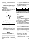
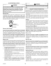
HORIZONTAL INSTALLATIONS
Filters must be installed in either the central return register or in
the return air duct work.
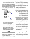
XI. SEQUENCE OF OPERATION
(INTEGRATED IGNITION CONTROL)
Refer to Timing Charts for sequencing.
The normal power up sequence is as follows:
• 115 VAC power applied to furnace.
• Integrated control module performs internal checks.
• Integrated control module flashes LED lights.
• Integrated control module monitors safety circuits
continuously.
• Furnace awaits call from thermostat.
NORMAL HEATING SEQUENCE
• R and W1 (or R and W1/W2) thermostat contacts close,
initiating a call for heat.
• Integrated control module performs safety circuit checks.
• Induced draft blower is energized on high speed for a 15-
second prepurge. Humidifier terminals are energized with
induced draft blower.
• Induced draft blower steps to low speed following prepurge.
Low stage pressure switch contacts are closed.
• Igniter warm up begins upon step to low speed and presence
of closed low stage pressure switch contacts.
• Gas valve opens at end of igniter warm up period,
delivering gas to burners and establishing flame.
• Integrated control module monitors flame presence. Gas
valve will remain open only if flame is sensed.
• If the thermostat call is for low heat, gas valve and induced
draft blower will continue on low stage. If the call is for high
heat, the gas valve and induced draft blower will change to
high stage.
• Circulator blower is energized on the appropriate heat speed
following a fixed thirty second blower on delay. The circulator
blower requires 30 seconds to ramp up to full speed.
Electronic air cleaner terminals are energized with circulator
blower.
• Furnace is now operating on the specified stage called for
by the two-stage thermostat.
• Furnace runs, integrated control module monitors safety
circuits continuously.
• If the two-stage thermostat changes the call from low heat
to high heat, the integrated control module will immediately
switch the induced draft blower, gas valve, and circulator
blower to their high stage settings.
• If the two-stage thermostat changes the call from high heat
to low heat, the control will immediately switch the induced
draft blower and gas valve to their low stage settings. The
circulator blower will remain on high heating speed for thirty
seconds before switching to the low heat circulating speed.
• R and W1 (or R and W1/W2) thermostat contacts open,
completing the call for heat.
• Gas valve closes, extinguishing flame.
• Induced draft blower is de-energized following a fifteen
second post purge. Humidifier terminals are de-energized.
• Circulator blower continues running for the selected heat
off delay period (90, 120, 150 or 180 seconds). The speed
run during this period depends on the last heat call provided
by the thermostat.
If the last call for heat was a call for high heat, the air
circulating motor will run on the high heating speed for thirty
seconds and then switch to the low heating speed for the
balance of the heat off delay period
• Electronic air cleaner terminals is de-energized
• Circulator blower ramps down to OFF during the 30 seconds
following the heat off delay period.
• Furnace awaits next call from thermostat.
NORMAL COOLING SEQUENCE - INTEGRATED IGNITION CON-
TROL
• R and YLO/G or Y/G thermostat contacts close, initiating a
call for cool.