


28
IO-247A 12/04
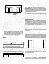
UPRIGHT FILTER REMOVAL
To remove filters from an external filter rack in an upright upflow
installation, follow the directions provided with external filter rack
kit.
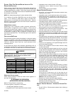
Clean, wash and dry a permanent filter. When using a metal filter,
both sides should be sprayed with a dust adhesive as recommended
on adhesive container. Spray adhesives for use with permanent
metal filters can be found at some hardware stores. BE SURE
AIRFLOW DIRECTION ARROW POINTS TOWARDS THE
BLOWER.
Inspect filter. If your dirty filter is the disposable type, replace dirty
with the same type and size filter. If your dirty filter is a permanent
metal filter, clean as follows:
• Wash, rinse, and dry the permanent filters. Both sides should
then be sprayed with a filter adhesive as is recommended
on the adhesive container. Many hardware stores stock
spray adhesives for use with permanent filters.
• If badly torn or uncleanable, these filters must be replaced
by equal size permanent, high velocity filters. Throwaway
filters must not be used as replacement for permanent filters.
Under normal use, permanent filters should last for several
years.
INDUCED DRAFT AND CIRCULATOR BLOWER MOTORS
The bearings in the induced draft blower and circulator blower
motors are permanently lubricated by the manufacturer. No further
lubrication is required. Check motor windings for accumulation of
dust which may cause overheating. Clean as necessary.
FLAME SENSOR (QUALIFIED SERVICER ONLY)
Under some conditions, the fuel or air supply can create a nearly
invisible coating on the flame sensor. This coating acts as an
insulator causing a drop in the flame sense signal. If the flame
sense signal drops too low the furnace will not sense flame and
will lock out. The flame sensor should be carefully cleaned by a
qualified servicer using emery cloth or steel wool. Following
cleaning, the flame sense signal should be as indicated in the
Specifications Sheet.
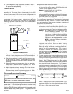
IGNITER (QUALIFIED SERVICER ONLY)
If the igniter and the surrounding air are at about 70°F and the
igniter wires are not connected to any other electrical components,
the resistance of the igniter should not exceed 200 ohms. If it does,
the igniter should be replaced.
BURNERS
WARNING
T
O PREVENT PERSONAL INJURY OR DEATH, DO NOT REMOVE ANY INTERNAL
COMPARTMENT COVERS OR ATTEMPT ANY ADJUSTMENT.
E
LECTRICAL
COMPONENTS ARE CONTAINED IN BOTH COMPARTMENTS.
C
ONTACT A
QUALIFIED SERVICE AGENT AT ONCE IF AN ABNORMAL FLAME APPEARANCE
SHOULD DEVELOP.
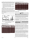
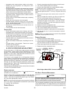
Periodically during the heating season make a visual check of the
burner flames. Turn the furnace on at the thermostat. Wait a few
minutes, since any dislodged dust will alter the normal flame
appearance. Flames should be stable, quiet, soft and blue with
slightly orange tips. They should not be yellow. They should extend
directly outward from the burner ports without curling downward,
floating or lifting off the ports.
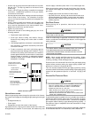
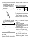
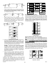
CLEANING (QUALIFIED S ERVICER O NLY)
1. Shut off electric power and gas supply to the furnace.
2. Remove screws securing manifold to burner bracket.
Slightly pull manifold out and away from burner bracket.
Burners will drop. Re-secure manifold to burner bracket.
3. Tilt burners to slotted side of burner bracket. Rotate burners
clockwise to remove.
4. Use bottle brush to clean burner insert and inside of burner.
5. Replace burner (opposite of removal). Ensure burners are
fully seated on burner bracket tabs and are properly aligned.
6. Turn on electric power and gas supply to the furnace.
7. Check furnace for proper operation. Refer to “Operational
Checks” section to verify burner flame characteristics.
XVII. BEFORE LEAVING AN INSTALLATION
• Cycle the furnace with the thermostat at least three times.
Verify cooling and fan only operation.
• Review the Owner’s Manual with the homeowner and
discuss proper furnace operation and maintenance.
• Leave literature packet near furnace.
XVIII. REPAIR AND REPLACEMENT PARTS
• When ordering any of the listed functional parts, be sure to
provide the furnace model, manufacturing, and serial
numbers with the order.
• Although only functional parts are shown in the parts list, all
sheet metal parts, doors, etc. may be ordered by description.
• Parts are available from your Amana distributor.
Functional Parts List-
Single Stage Gas Valve Blower/Box Gasket
Natural Gas Orifice Rollout Limit Switch
Propane Gas Orifice Auxiliary Limit Switch
Burner Heat Exchanger
Hot Surface Igniter Door Switch
Flame Sensor Transformer
Gas Manifold Blower Wheel
Ignition Control Blower Housing
Blower Mounting Bracket Blower Cutoff
Pressure Switch Blower Motor
Pressure Switch Hose Motor Mount Bracket
Induced Draft Blower Capacitor
Collector Box