


15
IO-247A 12/04
burner compartment will need to move the juction box
directly over.
4. Attach the junction box to the right side of the furnace, using
the screws removed in step 2.
5. Check the location wiring. Confirm that it will not be
damaged by heat from the burners or by the rotation of the
fan. Also confirm that wiring location will not interfere with
filter removal or other maintenance.
After the junction box is in the desired location, use washers to
connect field-supplied conduit to the junction box in accordance
with NEC and local codes. Connect hot, neutral, and ground wires
as shown in the furnace wiring diagram. The wires and ground
screw are located in the furnace junction box.
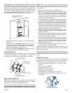
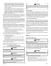
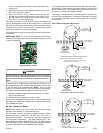
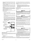
Low voltage wires may be connected to the terminal strip as shown
in Figure 12.
IMPORTANT NOTE: To avoid possible equipment malfunction,
route the low voltage wires to avoid interference with filter removal
or other maintenance.
Integrated Ignition Control
WARNING
T
O AVOID THE RISK OF INJURY, ELECTRICAL SHOCK OR DEATH, THE FURNACE
MUST BE ELECTRICALLY GROUNDED IN ACCORDANCE WITH LOCAL CODES OR,
IN THEIR ABSENCE, WITH THE LATEST EDITION OF THE
N
ATIONAL
E
LECTRIC
CODE.
To ensure proper unit grounding, the ground wire should run from
the furnace ground screw located inside the furnace junction box
all the way back to the electrical panel. NOTE: Do not use gas
piping as an electrical ground. To confirm proper unit grounding,
turn off the electrical power and perform the following check.
1. Measure resistance between the neutral (white) connection
and one of the burners.
2. Resistance should measure 10 ohms or less.
This furnace is equipped with a blower door interlock switch which
interrupts unit voltage when the blower door is opened for servicing.
Do not defeat this switch.
24 VOLT THERMOSTAT WIRING
NOTE: Wire routing must not interfere with circulator blower
operation, filter removal, or routine maintenance.
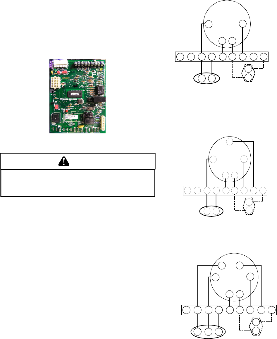
As a two-stage furnace, the furnace integrated control module
provides terminals for both “W1” and “W2”, and “YLO” and “Y”
thermostat connections. This allows the furnace to support the
following system applications: ‘Two-Stage Heating Only’, ‘Two-
Stage Heating with Single-Stage Cooling’, and ‘Two-Stage Heating
with Two-Stage Cooling’. Refer to the following figures and table
for proper connections to the integrated control module.
Low voltage connections can be made through either the right or
left side panel. Thermostat wiring entrance holes are located in the
blower compartment. The following figure shows connections for
a “heat only” system and “heat/cool system”.
This furnace is equipped with a 40 VA transformer to facilitate use
with most cooling equipment. Consult the wiring diagram, located
on the blower compartment door, for further details of 115 Volt and
24 Volt wiring.
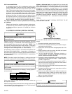
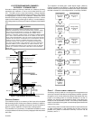
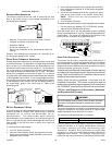
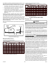
SINGLE STAGE THERMOSTAT APPLICATION
W
G
Y
Single-Stage Heating with Single-Stage Cooling
R
B/C G R W1 W2O
YLO
Y
DEHUM
TWIN
Y C
NEU
HOT
Furnace Integrated
Control Module
Thermostat
Single-Stage Heating with
Single-Stage Cooling
()
Remote
Condensing Unit
(Single-Stage Cooling)
Dehumidistat
[Optional]
NOTE:
To apply a single-stage heating thermostat, the
thermostat selector jumper on the integrated Control
module
must
be set on single stage.
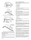
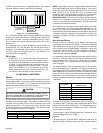
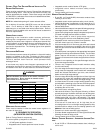
W1
G
Y
Two-Stage Heating with Single-Stage Cooling
R
W2
B/C G R W1 W2O
YLO
Y
DEHUM
TWIN
Y C
NEU
HOT
Furnace Integrated
Control Module
Thermostat
Two-Stage Heating
with
Single-Stage Cooling
()
Remote
Condensing Unit
(Single-Stage Cooling)
Dehumidistat
[Optional]
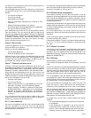
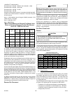
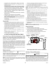
G
Y
Two-Stage Heating with Two-Stage Cooling
R
B/C G R W1 W2O
YLO
Y
DEHUM
TWIN
NEU
HOT
Furnace Integrated
Control Module
Thermostat
Two-Stage Heating
with
Two-Stage Cooling
()
Remote
Condensing Unit
(Two-Stage Cooling)
Dehumidistat
[Optional]
Y C
YLO
YLO
W2
W1