


30
IO-247A 12/04
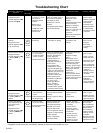
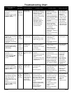
Troubleshooting Chart
Fault Description(s)
Symptoms of Abnormal
Operation
4
4 FLASHES
Associated
LED Code
2
•Circulator blower runs
continuously. No furnace
operation.
•Integrated control module
diagnostic LED is flashing
FOUR (4) flashes.
7
7 FLASHES
•Normal furnace
operation.
•Integrated control
module diagnostic LED
is flashing SEVEN (7)
flashes.
• Furnace fails to operate.
• Integrated control module
diagnostic LED is flashing
continuously.
C
CONTINUOUS
FLASHING
•Primary limit
circuit is open.
•Polarity of 115
volt power is
reversed.
•Flame sense
microamp signal is
low.
•Insufficient conditioned air
over the heat exchanger.
Blocked filters, restrictive
ductwork, improper
circulator blower speed,
or failed circulator blower.
•Flame rollout.
•Misaligned burners,
blocked flue and/or air
inlet pipe, or failed
induced draft blower.
•Loose or improperly
connected wiring.
Possible Causes Corrective Action Cautions and Notes
•Check filters and
ductwork for blockage.
Clean filters or remove
obstruction.
•Check circulator blower
speed and performance.
Correct speed or replace
blower if necessary.
•Check burners for proper
alignment.
•Check flue and air inlet
piping for blockage,
proper length, elbows,
and termination. Correct
as necessary.
•Check induced draft
blower for proper
performance. Replace, if
necessary.
•Tighten or correct wiring
connection.
•Turn power OFF
prior to repair.
•See Product Data
Bulletin for
allowable rise
range and proper
circulator speed.
See “Vent/Flue
Pipe” section for
piping details.
•Replace pressure
switch with proper
replacement part.
•Polarity of 115 volt AC
power to furnace or
integrated control module
is reversed.
•Poor unit ground.
•Flame sensor is coated/
oxidized.
•Flame sensor incorrectly
positioned in burner
flame.
•Lazy burner flame due to
improper gas pressure or
combustion air.
•Review wiring diagram to
correct polarity.
•Verify proper ground.
Correct if necessary.
•Check and correct wiring.
•Sand flame sensor is
coated/oxidized.
•Inspect for proper sensor
alignment.
•Check inlet air piping for
blockage, proper length,
elbows, and termination.
•Compare current gas
pressure to rating plate
info. Adjust as needed.
•Turn power OFF
prior to repair.
•Turn power OFF
prior to repair.
•Sand flame
sensor with
emery clot.
•See “Vent/Flue
Pipe” section for
piping details.
•See rating plate
for proper gas
pressure.
• Inspect
pressure
switch
hose.
Repair, if necessary.
• Inspect flue and/or inlet
air piping for blockage,
proper length, elbows,
and termination.
Check
drain
system.
Correct
as
necessary.
• Correct pressure switch
setpoint or
contact
motion.
• Tighten
or
correct
wiring
connection.
9
9 FLASHES
•Furnace not operating.
•Integrated control module
diagnostic LED is flashing
EIGHT (8) flashes.
• Furnace operating on
low stage gas with high
stage induced draft blower
• High stage circulator
blower (temperature, of
conditioned air, lower than
typical).
•Integrated control module
diagnostic LED is flashing
NINE (9) flashes.
8
8 FLASHES
• High stage
pressure switch
circuit does not
close in response
to high stage
induced draft
blower operation.
•Problem with
igniter circuit.
•Improperly
connected igniter
•Bad igniter
•Poor unit ground
• Pressure switch hose
blocked, pinched or
connected improperly.
• Blocked flue and/or inlet air
pipe, blocked drain system,
or weak induced draft
blower.
• Incorrect pressure switch
setpoint or malfunctioning
switch contacts.
• Loose or improperly
connected wiring.
•Check and correct wiring
from integrated control
module to igniter
•Replace bad igniter
•Check and correct unit
ground
wiring
•Turn power OFF
prior to repair.
•Replace igniter
with proper
silicon nitride
replacement part.
•Turn power OFF
prior to repair.
•Replace pressure
switch with
proper
replacement part.
• Integrated control module
diagnostic LED is flashing
FIVE (5) times.
•Induced draft blower and
circulator blower run
continuously. No furnace
operation.
• Flame sensed with
no call for heat.
•Correct short at flame
sensor or in flame
sensor wiring.
•Check for lingering
flame
•Verify proper operation
of gas valve
•Short to ground in flame
sense circuit.
•Lingering burner flame.
•Slow closing gas valve
•Turn power OFF
prior to repair.
5
5 FLASHES