20
IO-247A 12/04
For satisfactory operation, propane gas pressure must be 11 inch
WC at the furnace manifold with all gas appliances in operation.
Maintaining proper gas pressure depends on three main factors:
1. Vaporization rate, depending on temperature of the liquid,
and “wetted surface” area of the container or containers.
2. Proper pressure regulation. (Two-stage regulation is
recommended for both cost and efficiency).
3. Pressure drop in lines between regulators, and between
second stage regulator and the appliance. Pipe size will
depend on length of pipe run and total load of all
appliances.
Complete information regarding tank sizing for vaporization,
recommended regulator settings, and pipe sizing is available from
most regulator manufacturers and propane gas suppliers.
Since propane gas will quickly dissolve white lead and most
standard commercial compounds, special pipe dope must be used.
Shellac-based compounds resistant to the actions of liquefied
petroleum gases such as Gasolac
®
, Stalactic
®
, Clyde’s
®
or John
Crane
®
are satisfactory.
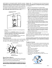
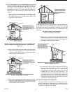
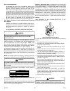
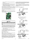
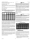
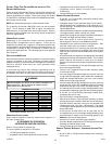
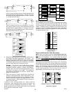
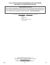
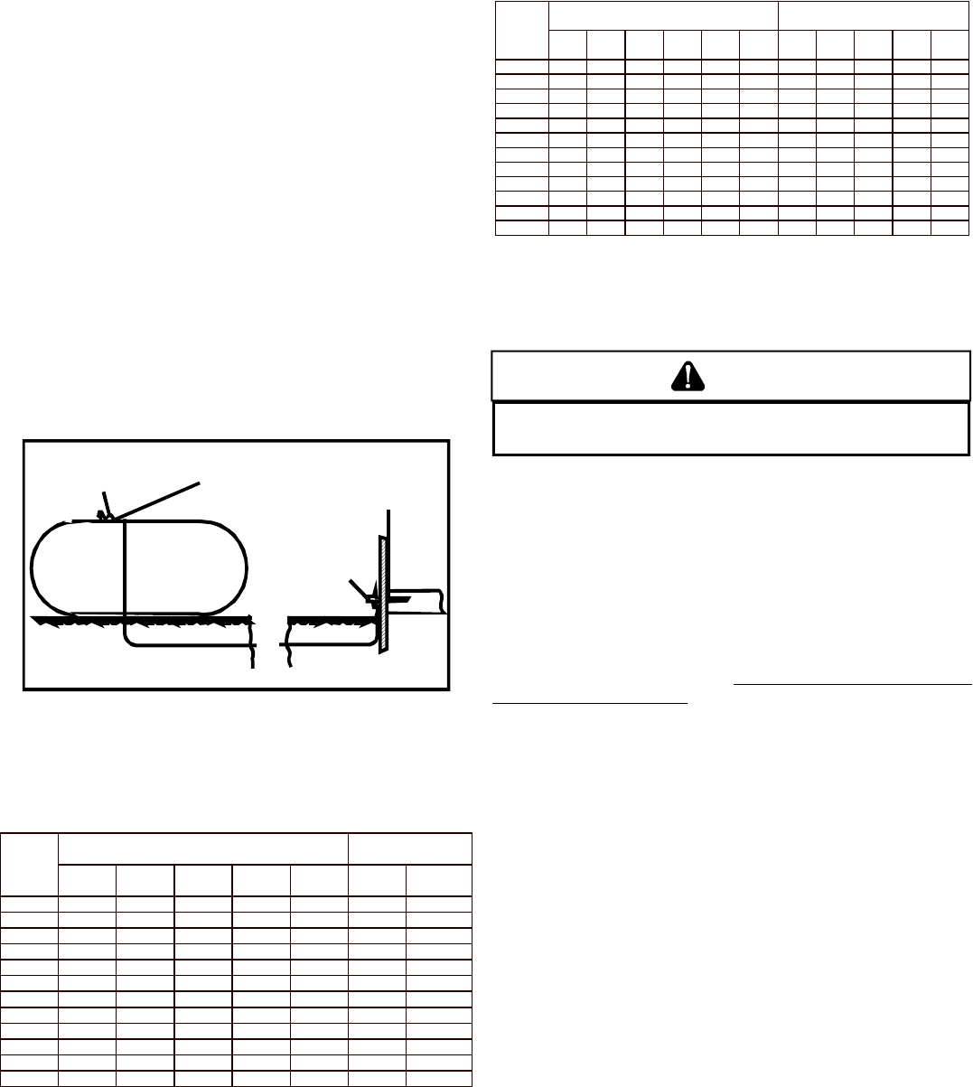
Refer to the following illustration for typical propane gas installations
and piping.
200 PSIG
Maximum
5 to 15 PSIG
(20 PSIG Max.)
Continuous
11" W.C.
Second Stage
Regulator
First Stage
Regulator
Propane Gas Installation (Typ.)
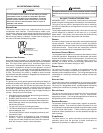
PROPANE GAS PIPING CHARTS
Sizing Between First and Second Stage Regulator*
Maximum Propane Capacities listed are based on 2 psig pressure drop at 10 psig setting.
Capacities in 1,000 BTU/hour.
Pipe or Nominal Pipe Size
Tubing Tubing Size, O.D. Type L Schedule 40
Length, 3/8" 1/2" 5/8" 3/4" 7/8" 1/2" 3/4"
Feet
10 730 1,700 3,200 5,300 8,300 3,200 7,500
20 500 1,100 2,200 3,700 5,800 2,200 4,200
30 400 920 2,000 2,900 4,700 1,800 4,000
40 370 850 1,700 2,700 4,100 1,600 3,700
50 330 770 1,500 2,400 3,700 1,500 3,400
60 300 700 1,300 2,200 3,300 1,300 3,100
80 260 610 1,200 1,900 2,900 1,200 2,600
100 220 540 1,000 1,700 2,600 1,000 2,300
125 200 490 900 1,400 2,300 900 2,100
150 190 430 830 1,300 2,100 830 1,900
175 170 400 780 1,200 1,900 770 1,700
200 160 380 730 1,100 1,800 720 1,500
To convert to capacities at 15 psig settings - multiply by 1.130
To convert to capacities at 5 psig settings - multiply by 0.879
Sizing Between Single or Second Stage Regulator and Appliance*
Maximum Propane Capacities Listed are Based on 1/2" W.C. pressure drop at 11" W.C. setting.
Capacities in 1,000 BTU/hour.
Pipe or Nominal Pipe Size
Tubing Tubing Size, O.D. Type
Schedule 4
Length, 3/8" 1/2" 5/8" 3/4" 7/8" 1-1/8" 1/2" 3/4" 1" 1-1/4
1-1/2
Feet
10 39 92 199 329 501 935 275 567 1,071 2,205 3,307
20 26 62 131 216 346 630 189 393 732 1,496 2,299
30 21 50 107 181 277 500 152 315 590 1,212 1,858
40 19 41 90 145 233 427 129 267 504 1,039 1,559
50 18 37 79 131 198 376 114 237 448 913 1,417
60 16 35 72 121 187 340 103 217 409 834 1,275
80 13 29 62 104 155 289 89 185 346 724 1,066
100 11 26 55 90 138 255 78 162 307 630 976
125 10 24 48 81 122 224 69 146 275 567 866
150 9 21 43 72 109 202 63 132 252 511 787
200 8 19 39 66 100 187 54 112 209 439 665
250 8 17 36 60 93 172 48 100 185 390 590
*Data in accordance with NFPA pamphlet NO. 54
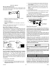
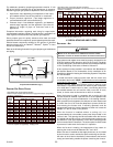
X. CIRCULATING AIR AND FILTERS
DUCTWORK - AIR
FLOW
WARNING
N
EVER ALLOW THE PRODUCTS OF COMBUSTION, INCLUDING CARBON
MONOXIDE, TO ENTER THE RETURN DUCTWORK OR CIRCULATION AIR SUPPLY.
Duct systems and register sizes must be properly designed for the
CFM and external static pressure rating of the furnace. Ductwork
should be designed in accordance with the recommended methods
of “Air Conditioning Contractors of America” Manual D.
A duct system must be installed in accordance with Standards of
the National Board of Fire Underwriters for the Installation of Air
Conditioning, Warm Air Heating and Ventilating Systems. Pamphlets
No. 90A and 90B.
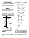
A closed return duct system must be used, with the return duct
connected to the furnace. NOTE:
Ductwork must never be attached
to the back of the furnace. Supply and return connections to the
furnace may be made with flexible joints to reduce noise
transmission. To prevent the blower from interfering with combustion
air or draft when a central return is used, a connecting duct must
be installed between the unit and the utility room wall. A room,
closet, or alcove must not be used as a return air chamber.
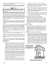
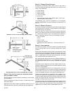
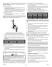
When the furnace is used in connection with a cooling unit, the
furnace should be installed in parallel with or on the upstream side
of the cooling unit to avoid condensation in the heating element.
With a parallel flow arrangement, the dampers or other means used
to control the flow of air must be adequate to prevent chilled air
from entering the furnace and, if manually operated, must be
equipped with means to prevent operation of either unit unless the
damper is in the full heat or cool position.
When the furnace is installed without a cooling coil, it is
recommended that a removable access panel be provided in the
outlet air duct. This opening shall be accessible when the furnace
is installed and shall be of such a size that the heat exchanger can
be viewed for visual light inspection or such that a sampling probe
can be inserted into the airstream. The access panel must be made
to prevent air leaks when the furnace is in operation.
When the furnace is heating, the temperature of the return air
entering the furnace must be between 55°F and 100°F.
When a furnace is installed so that supply ducts carry air circulated
by the furnace to areas outside the space containing the furnace,
the return air shall also be handled by a duct sealed to the furnace
casing and terminating outside the space containing the furnace.