


23
IO-247A 12/04
manifold pressure, use the following procedure.
1. Turn OFF gas to furnace at the manual gas shutoff valve
external to the furnace.
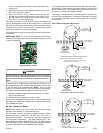
2. Connect a calibrated water manometer (or appropriate gas
pressure gauge) at the gas valve outlet pressure tap (refer
to gas valve figure in previous section).
3. Turn ON the gas supply and operate the furnace.
4. Measure gas manifold pressure with burners firing. Adjust
manifold pressure according to the table below:
Range Nominal
Natural Low Stage 1.6 - 2.2" w.c. 1.9" w.c.
High Stage 3.0 - 3.6" w.c. 3.5" w.c.
Propane Low Stage 5.7 - 6.3" w.c. 6.0" w.c.
High Stage 9.7 - 10.3" w.c. 10.0" w.c.
Manifold Gas Pressure
Gas
The final manifold pressure must not vary more than ± 0.3 “ w.c.
from the above specified pressures. Any necessary major changes
in gas flow rate should be made by changing the size of the burner
orifice.
5. To adjust the gas valve pressure regulator, remove the
regulator cap
6. Turn the adjustment screw clockwise to increase the
pressure, or counterclockwise to decrease the pressure.
7. Securely replace the regulator cap.
8. Turn OFF gas to furnace at the manual shutoff valve and
disconnect manometer.
9. Reinstall gas valve outlet pressure tap plug before turning
on gas to furnace.
GAS INPUT RATE MEASUREMENT (NATURAL GAS ONLY)
The gas input rate to the furnace must never be greater than that
specified on the unit rating plate. To measure natural gas input
using the gas meter, use the following procedure.
1. Turn OFF the gas supply to all other gas-burning appliances
except the furnace.
2. While the furnace is operating, time and record one complete
revolution of the smallest gas meter dial.
3. Calculate the number of seconds per cubic foot (sec/ ft
3
) of
gas being delivered to the furnace. If the dial is a one cubic
foot dial, divide the number of seconds recorded in step 2
by one. If the dial is a two cubic foot dial, divide the number
of seconds recorded in step 2 by two.
4. Calculate the furnace input in BTUs per hour (BTU/ hr). Input
equals the sum of the installation’s gas heating value and a
conversion factor (hours to seconds) divided by the number
of seconds per cubic foot. The measured input must not be
greater than the input indicated on the unit rating plate.
EXAMPLE:
Installation’s gas heating (HTG) value: 1,000 BTU/ft
3
(Obtained from gas supplier)
Installation’s seconds per cubic foot: 34 sec/ ft
3
Conversion Factor (hours to seconds): 3600 sec/hr
Input = (Htg. value x 3600) ÷ seconds per cubic foot
Input = (1,000 BTU/ft
3
x 3600 sec/hr) ÷ 34 sec/ ft
3
Input = 106,000 BTU/hr
This measured input must not be greater than the input
indicated on the unit rating plate.
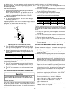
gas piping drip leg. The supply pressure must be measured with
the burners operating. To measure the gas supply pressure, use
the following procedure.
With Power and Gas Off:
1. Connect a water manometer or adequate gauge to the “inlet
pressure tap” of the gas valve.
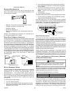
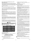
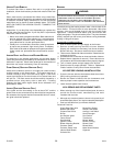
As an alternative method, inlet gas pressure can also be
measured by removing the cap from the drip leg and
installing a predrilled cap with a hose fitting (Figure 26).
With Power and Gas On:
2. Put furnace into heating cycle and turn on all other gas
consuming appliances.
If operating pressures differ from the Inlet Gas Supply Pressure
table below, make necessary pressure regulator adjustments, check
piping size, etc., and/or consult with local utility.
Gas Line
Gas
Shutoff
Valve
Gas Line
To Furnace
Drip Leg Cap
With Fitting
Manometer Hose
Manometer
Open To
Atmosphere
Measuring Inlet Gas Pressure (Alternate Method)
3. Turn ON the gas supply and operate the furnace and all
other gas consuming appliances on the same gas supply
line.
4. Measure furnace gas supply pressure with burners firing.
Supply pressure must be within the range specified in the
table below.
Natural Gas
Minimum: 5.0" w.c. Maximum:10.0" w.c.
Propane Gas
Minimum: 11.0" w.c. Maximum:13.0" w.c.
Inlet Gas Supply Pressure
If supply pressure differs from table, make the necessary
adjustments to pressure regulator, gas piping size, etc., and/or
consult with local gas utility.
5. Turn OFF gas to furnace at the manual shutoff valve and
disconnect manometer. Reinstall plug before turning on
gas to furnace.
6. Turn OFF any unnecessary gas appliances stated in step
3.
GAS MANIFOLD PRESSURE MEASUREMENT AND ADJUSTMENT
CAUTION
T
O PREVENT UNRELIABLE OPERATION OR EQUIPMENT DAMAGE, THE GAS
MANIFOLD PRESSURE MUST BE AS SPECIFIED ON THE UNIT RATING PLATE.
O
NLY MINOR ADJUSTMENTS SHOULD BE MADE BY ADJUSTING THE GAS VALVE
PRESSURE REGULATOR.
Only small variations in gas pressure should be made by adjusting
the gas valve pressure regulator. The manifold pressure must be
measured with the burners operating. To measure and adjust the