


14
IO-247A 12/04
WARNING
TO AVOID THE RISK OF INJURY, ELECTRICAL SHOCK OR DEATH, THE FURNACE
MUST BE ELECTRICALLY GROUNDED IN ACCORDANCE WITH LOCAL CODES OR,
IN THEIR ABSENCE, WITH THE LATEST EDITION OF THE
N
ATIONAL
E
LECTRIC
CODE.
WIRING HARNESS
The wiring harness is an integral part of this furnace. Field
alteration to comply with electrical codes should not be required.
Wires are color coded for identification purposes. Refer to the
wiring diagram for wire routings. If any of the original wire as
supplied with the furnace must be replaced, it must be replaced
with wiring material having a temperature rating of at least 105°
C. Any replacement wiring must be a copper conductor.
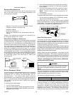
115 VOLT LINE CONNECTIONS
Before proceeding with electrical connections, ensure that the
supply voltage, frequency, and phase correspond to that specified
on the unit rating plate. Power supply to the furnace must be
NEC Class 1, and must comply with all applicable codes. The
furnace must be electrically grounded in accordance with local
codes or, in their absence, with the latest edition of The National
Electric Code, ANSI NFPA 70 and/or The Canadian Electric Code
CSA C22.1.
Use a separate fused branch electrical circuit containing properly
sized wire, and fuse or circuit breaker. The fuse or circuit breaker
must be sized in accordance with the maximum overcurrent
protection specified on the unit rating plate. An electrical
disconnect must be provided at the furnace location.
Line voltage wiring must enter into the junction box provided with
the furnace.
NOTE: Line polarity must be observed when making field
connections.
JUNCTION BOX RELOCATION
WARNING
E
DGES OF SHEET METAL HOLES MAY BE SHARP.
U
SE GLOVES AS A PRE-
CAUTION WHEN REMOVING HOLE PLUGS.
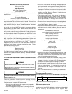
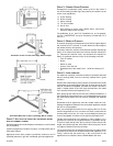
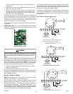
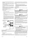
Line voltage connections can be made through either the right or
left side panel. The furnace is shipped configured for a left side
electrical connection. To make electrical connections through the
opposite side of the furnace, the junction box must be relocated
to the left side prior to making electrical connections. To relocate
the junction box, perform the following steps.
WARNING
T
O PREVENT PERSONAL INJURY OR DEATH DUE TO ELECTRIC SHOCK,
DISCONNECT ELECTRICAL POWER BEFORE INSTALLING OR SERVICING THIS
UNIT.
1. Remove both doors from the furnace.
2. Remove and save the screws holding the junction box to
the lef t side of the furnace.
3. Models that have the juction box located in the blower
compartment will need to rotate the junction box 180
degrees. Models that have the junction box located in the
include indoor swimming pools and chlorine bleaches, paint
strippers, adhesives, paints, varnishes, sealers, waxes
(which are not yet dried) and solvents used during
construction and remodeling. Various commercial and
industrial processes may also be sources of chlorine/
fluorine compounds.
• Heavier gauge 300 and 400 series stainless steel liners
were developed for use with oil or solid fuel appliances.
They are not suitable for use with gas-fired appliances.
Flexible liners specifically intended and tested for gas
applications are listed in the UL “Gas and Oil Equipment
Directory”. (UL Standard 1777).
For sizing of flexible liners, see Note 22 and the tables in the
National Fuel Gas Code NFPA 54/ANSI Z223.1 - latest edition
and in the National Standard of Canada, CAN/CSA B149.1 and
CAN/CSA B149.2 - latest editions and amendments.
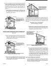
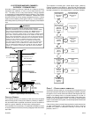
To install the liner, read and follow the liner manufacturer’s
instructions and your local codes. Excess liner length should be
pulled out of the chimney and cut off. Use caution when doing
this, as the cut edges of flexible liners may be sharp. Do not spiral
excess liner inside of the chimney. Support the liner as
recommended by the liner manufacturer.
Some manufacturers of flexible liners offer an insulation sleeve
designed to be added to the liner before it is installed in the
chimney. (Poured insulation, either vermiculite or other materials,
is no longer recommended.) Insulation will need to be added to
the flexible liner if:
• It is required by the liner manufacturer’s instructions.
• The previous liner was properly sized and installed, and
suffered from condensation damage.
• It is required by your local building codes.
Even if none of those three conditions exist which require additional
liner insulation, the installer may wish to consider it if:
• The local climate is very cold.
• The chimney is very tall.
• The vent connectors used are very long or have a large
number of elbows.
• Local experience indicates that flexible liners installed
without insulation are likely to have condensation problems.
Insulation must be selected and installed in accordance with the
liner manufacturer’s instructions.
Finally, cap the chimney and terminate the liner in accordance
with the liner manufacturer’s instructions.
VIII. ELECTRICAL CONNECTIONS
WARNING
T
O AVOID THE RISK OF ELECTRICAL SHOCK, WIRING TO THE UNIT MUST BE
POLARIZED AND GROUNDED.
WARNING
T
O AVOID INJURY, ELECTRICAL SHOCK OR DEATH, DISCONNECT ELECTRICAL
POWER BEFORE SERVICING OR CHANGING ANY ELECTRICAL WIRING.
CAUTION
L
ABEL ALL WIRES PRIOR TO DISCONNECTION WHEN SERVICING CONTROLS.
W
IRING ERRORS CAN CAUSE IMPROPER AND DANGEROUS OPERATION.
V
ERIFY PROPER OPERATION AFTER SERVICING.