-
80
-
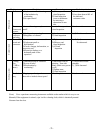
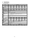
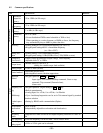
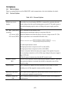
9-2 Common specifications
Item Specifications Remarks
Maximum
output fre-
quency
• 50 to 120Hz (in 1Hz steps)
Base
frequency
• 25 to 120Hz (in 1Hz steps)
Starting fre-
quency
• 1 to 6Hz (in 1Hz steps)
Setting
Carrier fre-
quency
• 0.75 to 15kHz
(Vector-distribution PWM control selectable at 7kHz or less)
When operating at a carrier frequency of 9kHz or above, the frequency
may automatically drop to 8kHz to protect the drive.
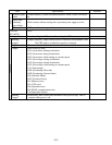
Accuracy • Analog setting:±1.0% of maximum frequency (at 25±10°C)
• Keypad panel setting:±0.01% of maximum frequency
(at –10 to +50°C)
Output frequency
Setting reso-
lution
• Analog setting: 1/256 of Maximum frequency
• Keypad panel setting: 0.1Hz(99.9Hz or less), 1Hz(100Hz or more)
Voltage/freq.
Characteristic
• Output voltage proportional to input voltage. Base frequency
adjustable from 25 to 120Hz.
Torque boost
• Manual setting by code 0 to 31.
(setting for variable torque load available)
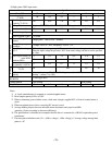
Starting torque • 150% or more (at 6Hz)
Control method
• Sinusoidal PWM control
(with simplified current-vibration suppression)
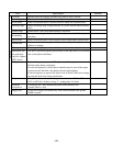
Operation
method
• Keypad operation: RUN or STOP key :
Input signal: Forward/Reverse/Stop command, Coast-to-stop
command, Trip command (External alarm),
Alarm reset
Frequency set-
ting
(Multistep)
(Linked opera-
tion)
• Keypad operation: ,Digital setting by or key
• Built-in potentiometer
• Analog input: 0 to +5Vdc, 0 to +10Vdc, 4 to 20mAdc
• Up to 4 multistep frequencies can be set in 2-bit external signal by terminal
function selection
• Setting by RS485 serial communication (Option)
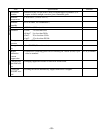
Acceleration/
deceleration
time
• 0.01 to 60.0s
(Independently adjustable acceleration and deceleration)
Frequency
limiter
• High and low limits can be set for output frequency between 0 to 100% in
Hz
Bias frequency • The bias frequency can be set from –100 to +100% in Hz.
Control
Gain (frequency
setting signal)
• 5Vdc or 10Vdc gain can be selected.


