


11
920-198-01
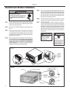
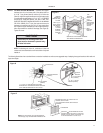
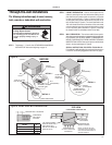
Figure D
" DOWN SLOPE
SUPPORTBRACKET
(ITEM #1)
#12Ax 2" SCREW
(ITEM #4)
1" x 4" OR 2" x 4" SPACER SHOULD BE USED
BETWEEN WALLAND BRACKET WHEN INSTALLED
ONALUMINUM,ASBESTOS OR VINYLSIDING
SUPPORT
BRACKET
10 – 24 FLAT WELD
NUT (ITEM #3)
10 – 24 x 1" HEX HD.
SCREW (ITEM #2)
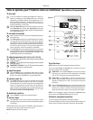
STEP 8 OUTSIDE SUPPORT MOUNTING – Assemble the support
ruofhtiwten i bacehtfosliarmottobehtot)1#metI(stekcarb
(4) 10-24 1" long screws (Item #2) and four (4) 10-24 Àat nuts
(Item #3). Adjust the support brackets to bring the bottom pads
in contact with the wall surface. (A
1"x4"or 2"x4"SPACER
SHOULD BE USED BETWEEN THE WALL AND THE
MUN IM ULANODELLATS NINEHWSTEKCARBTROPPUS
OR VINYL SIDING). Drill
5
»
32
" dia. pilot holes and secure the
metI(swercsgnol"2xA21#)2(owthtiwllawehtotste kcarb
"8/3etam i xorp panaedivorpotstekcarbtroppusehttsujdA.
)4#
.)DerugiFeeS(.eganiardrofedis tuoehtdrawotepolsnwod
Tighten all screws.
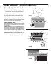
NOTE: The discharge air, return air,
condenser air inlets and
outlets must be unobstructed to avoid recirculation of rejected
heated air.
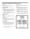
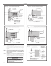
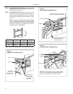
noit curts nocemarfdradnatsawohssnoitartsulligniwollofehT sehtgni tpadafosyawdetseggusemossallewsanoitallatsni upport bracket to thick walls and
large stone ledges.
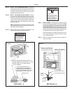
CENTER
CABINET IN
WINDOW SIDE
TO SIDE.
DRILL(3)
5
»
32
"
PILOT HOLES
AND INSTALL
(3) #12Ax
2" LONG
SCREWS
(ITEM #4)
WINDOW
SILL
LOCATE SILLPLATE GUIDE CHANNEL
JUST BACK OF WINDOW SILL
TOP
SUPPORT
ANGLE
PULL
WINDOW
SASH DOWN
BEHIND TOP
SUPPORT
ANGLE
SIDE
SUPPORT
ANGLE
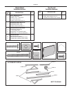
Figure C
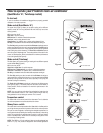
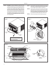
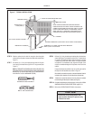
Figure E
MEASURE DISTANCE "B" TO INSIDE OFTHE
CHANNEL ON EACH SIDE
CUT HEREAND DISCARD CENTER WASTE
MATERIAL.
WINGBOARD
SUBTRACT
" FROM DIMENSION "B"AND
MEASURE FROM THE EDGE OF THE WING-
BOARD (ITEM # 8), MARK, SCOREAND CUT
WITH APPROPPRIATE CUTTING TOOL
NOTE: It is not necessary to cut the wingboard for
vertical height; only horizontal WIDTH Dimension “B”.
Instructions for mounting sleeve with
slope must be observed to prevent entry
of water into room.
NOTICE