


www.fmiproducts.com
116646-01J 21
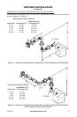
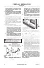
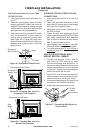
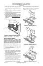
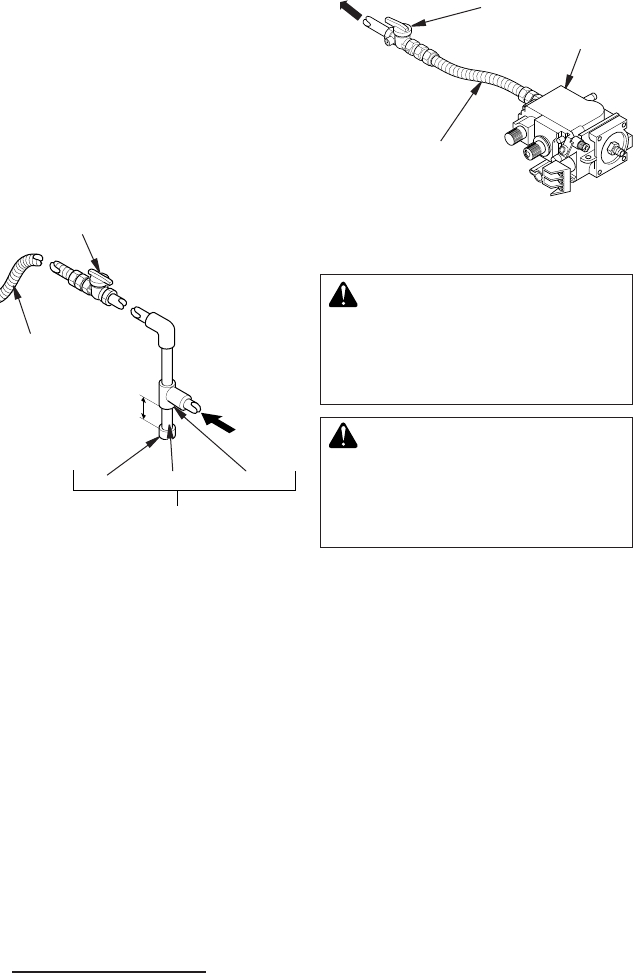
Figure 32 - Gas Connection
Equipment Shutoff Valve with
1/8" NPT Tap*
3" Minimum
Approved
Flexible Gas
Line
Cap Pipe Nipple Tee Joint
Sediment Trap/Drip Leg
Natural - From
Gas Meter (5.5"
W.C. to 10.5"
W.C. Pressure)
Propane/LP
From External
Regulator (11"
W.C. to 14"
W.C. Pressure)
* The equipment shutoff valve may be sup-
plied with the appliance or you can purchase
it from your retailer.
We recommend that you install a sediment
trap/drip leg in supply line as shown in Figure
32. Locate sediment trap/drip leg where it is
within reach for cleaning. Install in piping sys-
tem between fuel supply and replace. Locate
sediment trap/drip leg where trapped matter
is not likely to freeze. A sediment trap traps
moisture and contaminants. This keeps them
from going into replace gas controls. If sedi-
ment trap/drip leg is not installed or is installed
wrong, replace may not run properly.
FIREPLACE INSTALLATION
Continued
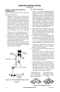
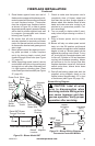
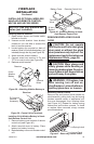
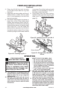
Figure 33 - Connecting Flexible Gas Line
to Millivolt Valve
CHECKING GAS CONNECTIONS
WARNING: Test all gas piping
and connections, internal and
external to unit, for leaks after
installing or servicing. Correct
all leaks at once.
WARNING: Never use an open
ame to check for a leak. Apply
noncorrosive leak detection uid
to all joints. Bubbles forming show
a leak. Correct all leaks at once.
PRESSURE TESTING GAS SUPPLY
PIPING SYSTEM
Test Pressures In Excess Of 1/2 PSIG
(3.5 kPa)
1.
Disconnect replace and its individual equip-
ment shutoff valve from gas supply piping
system. Pressures in excess of 1/2 psig (3.5
kPa) will damage replace gas regulator.
2. Cap off open end of gas pipe where equip-
ment shutoff valve was connected.
3.
Pressurize supply piping system by either
opening propane/LP supply tank valve for
propane/LP gas replace or opening main gas
valve located on or near gas meter for natural
gas replace or using compressed air.
4. Check all joints of gas supply piping sys-
tem. Apply noncorrosive leak detection
uid to all joints. Bubbles forming show a
leak. Correct all leaks at once.
5. Reconnect fireplace and equipment
shutoff valve to gas supply. Check recon-
nected ttings for leaks.
Flexible Gas Line
Do NOT Kink
Equipment
Shutoff
Valve
To Gas Supply
(Natural)
To External
Regulator
(Propane/LP)
Control Valve
CONNECTING FIREPLACE TO GAS
SUPPLY
Installation Items Needed
• 5/16" hex socket wrench or nut-driver
• sealant (resistant to propane/LP gas, not
provided)
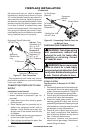
1. Open lower louver door panel by gently
pulling forward.
2. Route exible gas line (provided by in-
staller) from equipment shutoff valve to
replace. Route exible gas supply line
through one of the access holes on side
of replace.
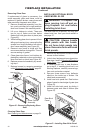
3. Attach exible gas line from gas supply to
control valve (see Figure 33).
4. Check all gas connections for leaks. See
Checking Gas Connections.