


www.fmiproducts.com
116646-01J 11
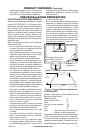
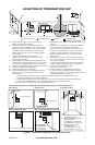
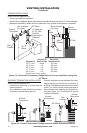
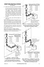
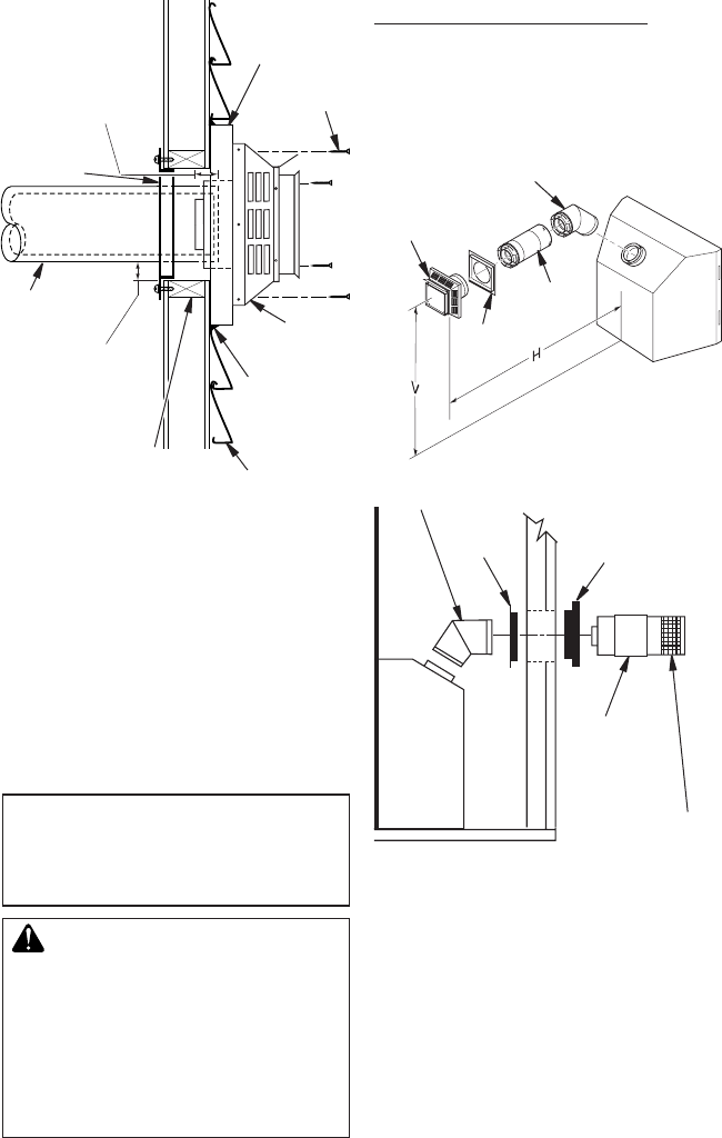
Figure 13 - Typical Horizontal
Termination Cap Mounting with
Additional Siding Standoff Installed
Siding
Standoff
Screws
High Wind
Termination
Apply Mastic
to Outside
Edge of
Standoff
Exterior Wall
with Vinyl Siding
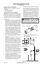
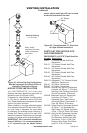
11
1
/
2
" x 11
1
/
2
"
Framed Opening
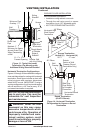
Maintain 1"
Minimum Air Space
Around Outer Pipe
When Penetrating
a Wall
Minimum Pipe
Overlap 1
1
/
4
"
Wall
Firestop
Direct Vent
Pipe
VENTING INSTALLATION
Continued
Horizontal Termination Congurations
Figures 14 through 18 show different congura-
tions and alternatives for venting with horizontal
termination. Each gure includes a chart with
critical minimum and maximum dimensions
which MUST be met. IMPORTANT: If using a
venting conguration of only horizontal venting
with no vertical run, a 1/4" rise for every 12" of
run toward termination is required.
NOTICE: Do not seal termination
cap to vent pipe. Cap must be
removable for vent inspection
and maintenance.
WARNING: Never run vent
downward as this may cause
excessive temperatures which
could cause a re. Operation of
improperly installed and main-
tained venting system could
result in serious injury, property
damage or loss of life.
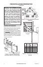
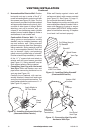
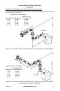
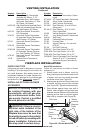
Vertical (V) Horizontal (H)
29
3
/
4
" 17" max.
Horizontal High
Wind Square
Termination
Wall
Firestop
45° Elbow
Figure 14 - Horizontal Termination
Conguration for Square or Round
Termination
45° Elbow
Wall
Firestop
Slide Ring
Over Elbow
to Complete
Connection
Exterior
Portion of Wall
Firestop (Round
Termination Only)
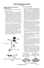
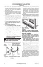
GROUND FLOOR INSTALLATION
Recommended Applications:
• Installation using cabinet surrounds
• Through the wall using round or square
termination (up to 12") adjustable pipe)
• NOT FOR CORNER INSTALLATION
Adjustable
Pipe 12"
Max.
Square Termination
Horizontal Round
Termination
Round Termination
(Kit HTK Shown)