


www.fmiproducts.com
116646-01J 17
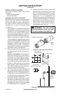
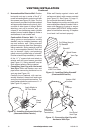
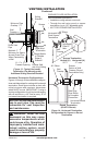
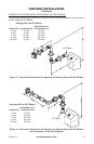
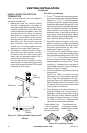
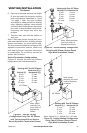
VENTING INSTALLATION
Continued
Number Description
VKC-58 Corner Vent Kit, Galvanized
(Includes 45° Elbow, 7"-12"
Adjustable Pipe, Wall Firestop,
Horizontal Termination, 6" Pipe,
90° Elbow, 18 Screws)
HHTK-58
High Wind Round Horizontal Termi-
nation Kit (Includes Round Termina-
tion, Wall Firestop, 45° Elbow)
HHT-58 High Wind Round Termination
Kit, Galvanized
HTK-58 Horizontal Round Termination
Kit (Includes Round Termination,
Wall Firestop, 45° Elbow)
HT-58 Horizontal Round Termination,
Galvanized
HTS-58 Horizontal Square Termination,
Galvanized
HTKS-58 Horizontal Square Termination
Kit (Includes: Square Termina-
tion, Wall Firestop, 45° Elbow)
HTS-58 Horizontal Square Termination,
Galvanized
VT-58 Vertical Round Termination,
Galvanized
FIREPLACE INSTALLATION
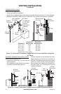
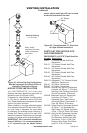
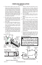
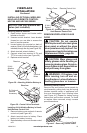
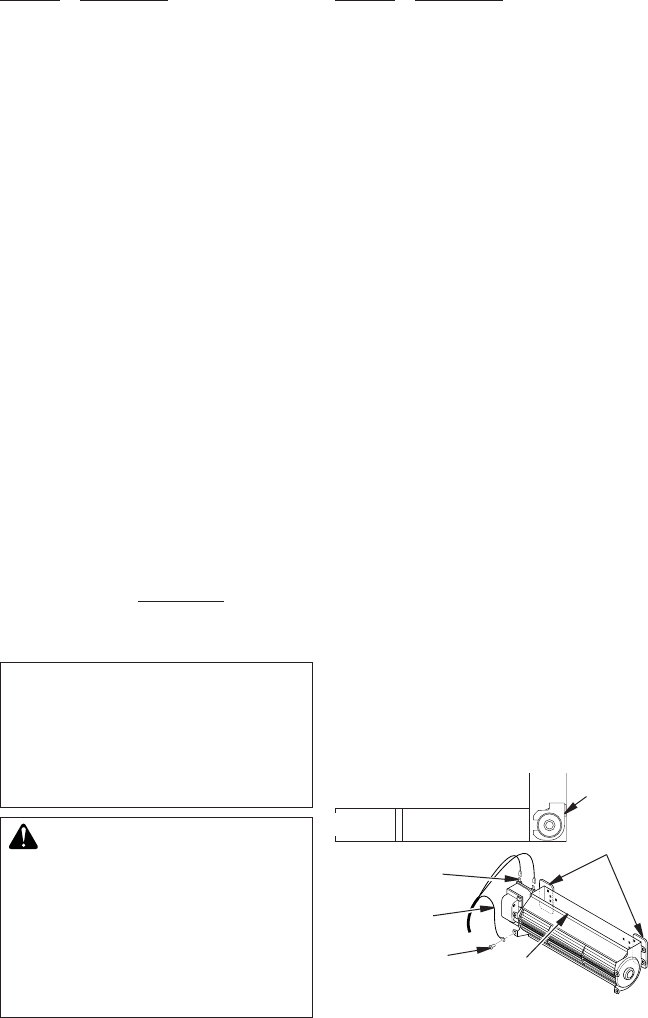
Figure 26 - Blower Model BK
Magnetic
Strips
Exhaust
Port
Screw
Green
Ground
Wire
Spade
Terminals
Side View
Lower Firebox
Cavity
Blower
Location
Number Description
ST-58-14 14" Snorkel Termination, Galva-
nized
ST-58-36
36" Snorkel Termination, Galvanized
SC-58 Storm Collar, Galvanized
WF-58 Wall Firestop, Galvanized
RF-58-6 Roof Flashing - 0 to 6/12 Pitch,
Galvanized
RF-58-12 Roof Flashing - 6/12 to 12/12
Pitch, Galvanized
VR-58 Vertical Restrictor, Galvanized
S-58 Vinyl Siding Standoff, Galvanized
WS-58 Wall Strap
CS-58 Cathedral Ceiling Support
FP-58 Firestop Plate
SF-58 Stucco Flashing - For use with
HTS-58
RF-58 Flat Roof Flashing
PF58-927
Flex Pipe Section 9" to 24"
PF58-1236
Flex Pipe Section 12" to 36"
PF58-1854
Flex Pipe Section 18" to 54"
VKF58-927
Flex Kit (Includes Flex Pipe Wall
Section 9" to 27", Firestop and
Horizontal Square Termination)
CHECK GAS TYPE
Use proper gas type for replace unit you are
installing. If your gas supply is not correct, do
not install replace. See retailer where you
purchased replace for proper replace ac-
cording to your gas type or to purchase gas
conversion kit (see Accessories, page 37).
INSTALLING OPTIONAL BLOWER
ACCESSORY
NOTICE: If installing blower in
an existing replace with gas
connections, shut off gas sup-
ply and disconnect heater from
gas supply. Contact a qualied
service person to do this.
WARNING: If there is a duplex
electrical outlet installed in the
right side of the bottom of the
replace base area, be sure that
the electrical power to the outlet is
turned off before proceeding with
blower installation. Failure to do
this may result in serious injury.
Model BK Installation
Follow all instructions provided in blower
accessory kit.
1. Attach power cord to blower motor by
rmly pushing two female terminals at end
of power cord onto two spade terminals
on blower motor (see Figure 26).
2. Attach green ground wire from power cord
to blower housing using screw provided
(see Figure 26). Tighten screws securely.
3. Place blower against lower rear wall of
rebox outer wrapper with exhaust port
directed upward. Blower will t inside back
opening and be held in position against
back wall by magnets (see Figure 26).