


www.fmiproducts.com
124978-01B18
INSTALLATION
Continued
and connections, internal and
external to unit, for leaks after
WARNING: Never use an
-
CAUTION: Make sure exter-
Connecting to Gas Supply,
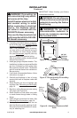
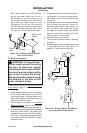
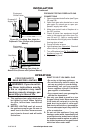
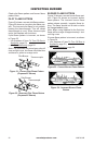
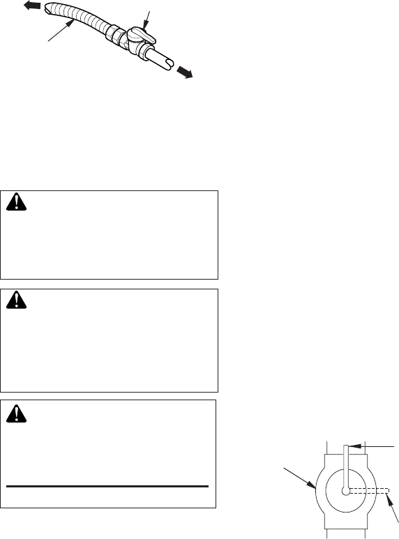
Figure 25 - Equipment Shutoff Valve
Open
Closed
Equipment
Shutoff
Valve
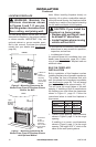
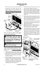
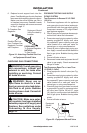
Figure 24 - Attaching Flexible Gas Line
to Equipment Shutoff Valve
Flexible Gas Line
from Fireplace Gas
Regulator Provided
with Fireplace
To Fireplace Gas
Regulator
Equipment Shutoff
Valve Provided by
Installer
To External Regulator
NATURAL
To Gas Supply
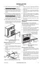
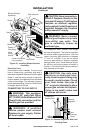
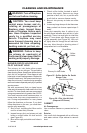
6. Replace branch support back into re-
place. Feed exible gas line into replace
base area while replacing branch support.
Make sure the entire exible gas line is
in replace base area. Reattach branch
support to replace with screws removed
in step 2, page 17.
1. Disconnect appliance with its appliance
main gas valve (control valve) and equip-
ment shutoff valve from gas supply piping.
Pressures in excess of 1/2 psig will dam-
age replace regulator.
2. Cap off open end of gas pipe where equip-
ment shutoff valve was connected.
3. Pressurize supply piping system by either
opening propane/LP supply tank valve
for propane/LP gas or opening main gas
valve located on or near gas meter for
natural gas, or using compressed air.
4. Check all joints of gas supply piping sys-
tem. Apply a noncorrosive leak detection
uid to gas joints. Bubbles forming show
a leak.
5. Correct all leaks at once.
6. Reconnect heater and equipment shutoff
valve to gas supply. Check reconnected
ttings for leaks.
1. Close equipment shutoff valve (see Fig-
ure 25).
2. Pressurize supply piping system by either
opening propane/LP supply tank valve
for propane/LP gas or opening main gas
valve located on or near gas meter for
natural gas, or using compressed air.
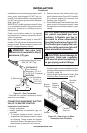
3. Check all joints from gas meter for natural
or propane/LP supply to equipment shut-
off valve (see Figures 26 and 27, page
19). Apply a noncorrosive leak detection
uid to gas joints. Bubbles forming show
a leak.
4. Correct all leaks at once.