


www.fmiproducts.com
124978-01B 15
INSTALLATION
Continued
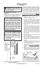
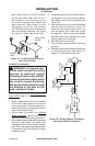
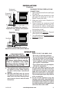
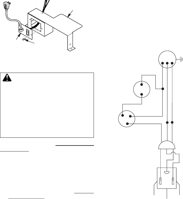
Figure 18 - Installing Switch Plate to
Valve Cover Shield
Switch
Plate
Screw
Valve Cover
Shield
WARNING: A licensed elec-
-
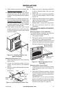
Follow instructions for Removing Valve
Cover Shield, page 13. Continue installation
as follows:
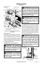
1. Install a snap bushing found in hardware
kit into one of the holes found on rear of
valve cover shield. The other hole is for a
strain relief clamp (not supplied) to secure
incoming electrical supply.
2. Follow steps 2 through 6 in Installing
Blower Assembly, page 14. Also remove
black wire from middle switch terminal 2.
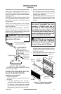
3. Remove black plastic strain relief and power
cord from switch plate. The power cord
supplied will not be used in built-in installa-
tions. Pop in the plastic snap bushing found
in hardware kit into the hole left by supply
cord/strain relief.
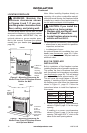
4. A licensed electrician must follow the wir-
ing diagram to connect incoming electri-
cal supply to fan kit wiring harness (see
Figure 19).
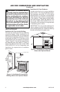
5. Plug power cord to the outlet receptacle
(not provided) as shown in Figure 18.
Wind the extra power cord and tie it up
with the plastic wire strap (see Figure
20, page 16). Set the power cord bundle
between the burner bracket and outer
casing, away from the burner.
6. Reinstall valve cover shield.
7. Test to make sure the blower is working
properly.
8. Reinstall upper louver assembly and hood
if previously removed, (see Figure 15,
page 13). Close lower louver door.
Red
Red
Fan Switch
(Auto/Off/On)
Blue
Blue
Thermostat
Switch
(N.O.)
Green
White
Green
White
On
1 1 0/115
V . A.C.
Blower
Motor
Black
Off
1
2
3
Auto
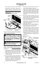
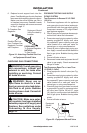
Figure 19 - Wiring Diagram For Blower
Accessory Built-In Installation
Note: When switch is in AUTO position,
fan will start after heater has run for a
few moments. Fan will continue to run
for several moments after heater has
been turned off. When switch is in the
ON position, fan will run until turned to
OFF. Reinstall upper louver assembly and
hood if previously removed, (see Figure
15, page 13). Close lower louver door.