


www.fmiproducts.com
124978-01B14
INSTALLATION
Continued
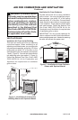
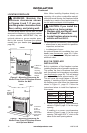
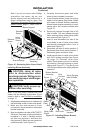
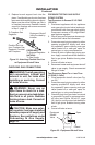
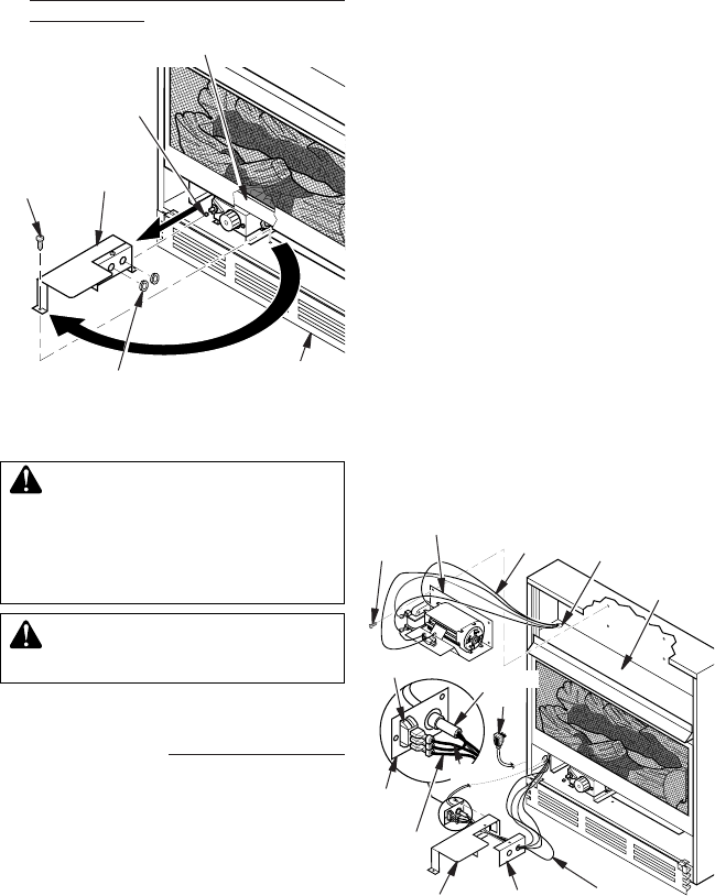
Figure 16 - Removing Valve Cover Shield
1
2
Remove
Screw
Valve
Cover
Shield
Shoulder
Screw
Branch Support
Snap Bushings
Bottom Louver
Assembly
4. Carefully disconnect green and white
wires at their insulated connectors.
5. In top of heater cabinet, locate 4 mounting
holes on outer casing. Align these 4 holes
with those on blower bracket assembly.
Attach blower bracket assembly to outer
casing with 4 #10 screws provided (see
Figure 17).
6. Route wire harness through hole in left
side of bafe. Pull wire harness through
lower opening above where valve shield
was removed (see Figure 17).
7. Insert 4 wire harnesses into one of the
round holes in rear of valve cover shield
and through rectangular hole in front of
shield (see Figure 17).
8. Reconnect red wire to switch position 3.
Reconnect blue wire to switch position 1.
Reconnect green and white wires.
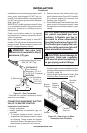
9. Install switch plate on valve cover shield
with 2 #10 screws provided (see Figure
18, page 15). Reinstall valve cover
shield. Route power cord out of cabinet
by inserting it through bushing on outer
casing (see Figure 17). Plug fan kit into
120-Volt grounded power supply and test
operation.
-
-
Note: If you are using a mantel with your
heater, use the following instructions. If your
heater is built-in, see For Built-In Installation
on page 15.
1. Install snap bushings found in hardware kit
into both holes in rear of valve cover shield.
2. Make sure the wire harness is firmly
connected to the terminals on the blower
bracket assembly.
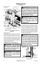
3. Note wire locations on back of AUTO/OFF/
ON switch. Terminals on back of switch are
numbered 1, 2, and 3. Carefully remove
red wire from terminal 1 and blue wire
from terminal 3. Black wire can remain on
middle terminal 2 (see Figure 17).
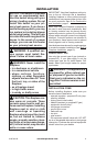
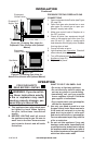
3
2
1
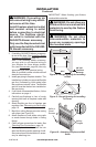
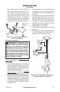
Figure 17 - Installing Blower Bracket
Assembly
Wire
Harness
Blower Bracket
Assembly
Screw
Valve Cover
Shield
Box Cover
Wire
Harness
Switch
Plate
Switch
Bafe
Wiring Routing
Hole in Bafe
Blue
Red
Power
Cord
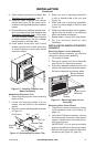
Note: If you do not have a short Phillips
screwdriver, the screen, log set, and
branch support must be removed so a
longer screwdriver may be used. See
Connecting Equipment Shutoff Valve to
Heater Control, page 17, steps 1 and 2.