


www.fmiproducts.com
124978-01B 13
INSTALLATION
Continued
9. Check all gas connections for leaks. See
Checking Gas Connections, page 18.
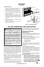
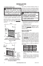
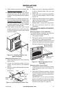
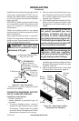
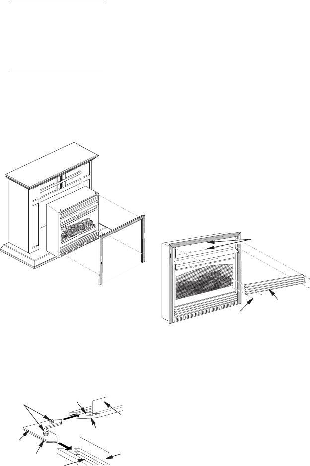
10. Carefully insert fireplace into cabinet
mantel (see Figure 13). Be careful not to
scratch or damage hearth base or cabinet
mantel.
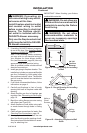
11. Place metal trim on shoulder screws locat-
ed on the side and top of the replace (see
Assembling Perimeter Trim). Firmly snap
trim over shoulder screws. Align replace
in mantel assembly so the trim overlaps
mantel evenly on all three sides.
12. Lower bottom louver door. Use 3" wood
screws provided with mantel accessory
to attach replace to base (see mantel
instruction sheet).
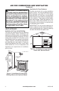
Side
Trim
Top Trim
Mitered Edge
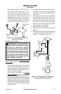
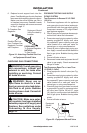
Figure 14 - Assembling Perimeter Trim
Shim
Set Screws
Adjusting
Plate
Slot
Slot
1. Remove packaging from three remaining
pieces of trim.
2. Locate two adjusting plates with set
screws, and two shims in the hardware
packet.
3. Align shim under adjusting plate as shown
in Figure 14.
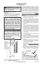
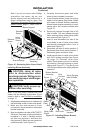
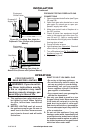
Figure 15 - Removing Upper Louver
Assembly
Upper Louver
Assembly
Black
Screws
Blower Bracket
Mounting Holes
Figure 13 - Installing Fireplace into
Mantel Assembly
4. Slide one end of adjusting plate/shim
in slot on mitered edge of top trim (see
Figure 14).
5. Slide other end of adjusting plate/shim
in slot on mitered edge of side trim (see
Figure 14).
6. While rmly holding edges of trim together,
tighten both set screws on the adjusting
plate with slotted screwdriver.
7. Repeat steps 1 through 6 for other corner.
8. Set trim assembly aside for later
installation.
To install the blower accessory, you must rst
remove the upper louver assembly.
1. Lift screen off heater.
2. Remove 4 screws from louver assembly
(see Figure 15). Save these screws.
3. Pull louver assembly straight out from the
cabinet. Be careful not to scratch the paint.
Set louver assembly and screws aside.
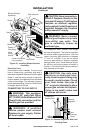
1. Open bottom louver assembly by swing-
ing the assembly down (see Figure 16,
page 14).
2. Using short Phillips screwdriver, remove
the screw under the center of the branch
support. Rotate valve cover shield clock-
wise and slide out.
IMPORTANT: Do not remove shoulder
screw on the left side of valve cover shield.
Slide the valve cover shield off of the shoul-
der screw (see Figure 16, page 14).