


www.fmiproducts.com
124978-01B12
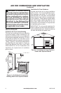
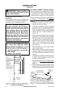
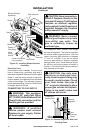
WARNING: Never modify or
cover the louvered slots on the
Installation
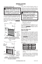
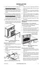
If placing mantel above built-in replace, you
must meet minimum clearance between man-
tel shelf and top of replace opening.
-
-
Follow all minimum clearances
NOTICE: If your installation does
not meet the minimum clear-
-
INSTALLATION
Continued
Refer to instructions provided with the mantel
for assembly instructions. Refer to the follow-
ing instructions for system installation. Refer
to instructions on page 6 for hood assembly.
Blower accessory should be installed prior
to mantel if it is being used (see Installing
Optional Blower Accessory GA3450TA,
page 13).
1. Assemble cabinet mantel as shown in
accessory instruction sheet.
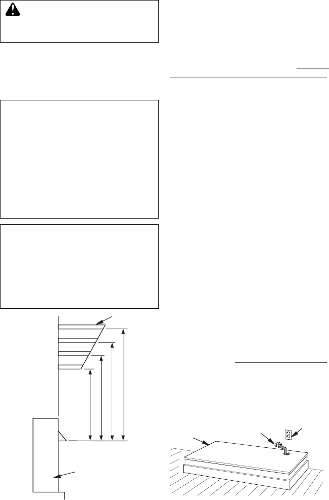
2. If blower is installed, install a properly
grounded, 120 volt three-prong electrical
outlet at replace location if an outlet is not
there. If possible, locate outlet so cabinet
mantel will cover it when installed (see
Figure 12).
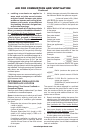
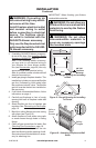
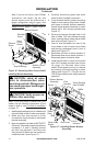
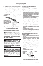
3. Place hearth base against wall at installa-
tion location. Cut an access hole in hearth
base to run gas line to replace (see Figure
12). Make sure to locate access hole so
cabinet mantel will cover it when installed.
Note: You can secure base to oor using
wood screws. Countersink screw heads
and putty over.
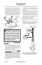
4. Route exible gas line through access
hole in hearth base.
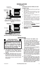
5. Center cabinet mantel on hearth base (see
Figure 13, page 13). Make sure mantel is
ush against wall and centered left to right
on base.
6. Use screws provided with mantel accessory
to attach mantel assembly to base (see
mantel instruction sheet).
7. Attach exible gas line to replace gas
regulator. See Connecting to Gas Supply,
page 16.
8. Route electrical cord(s) through access
holes in either side of replace with bushing.
Plug electrical cord(s) into electrical outlet.
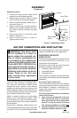
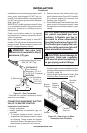
13"
16"
19"
21"
2
1
/
2
"
6"
8"
10"
Note:
A
ll vertical
measurements
are from top of
fireplace
opening to
bottom of
mantel shelf. All
measurements
are in inches.
Figure 11 - Minimum Mantel Clearances
for Built-In Installation
Mantel Shelf
Side of
Firebox
Figure 12 - Placing Hearth Base Against Wall
Hearth
Base
Electrical
Outlet
Pipe and Gas
Shutoff Valve