


www.fmiproducts.com
124978-01B 17
INSTALLATION
Continued
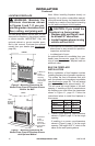
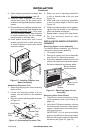
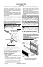
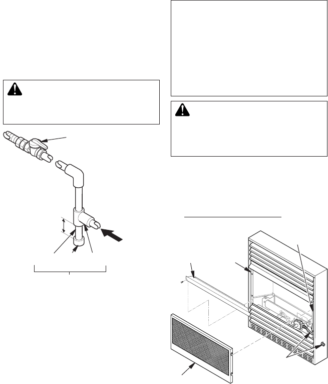
Installation must include an equipment shutoff
valve, union, and plugged 1/8" NPT tap. Lo-
cate NPT tap within reach for test gauge hook
up. NPT tap must be upstream from replace
(see Figure 22).
IMPORTANT: Install equipment shutoff valve
in an accessible location. Equipment shutoff
valve is for turning on or shutting off gas to
the appliance.
Check your building codes for any special
requirements for locating equipment shutoff
valve to replaces.
Apply pipe joint sealant lightly to male NPT
threads. This will prevent excess sealant from
going into pipe. Excess sealant in pipe could
result in clogged replace valves.
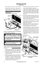
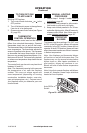
Figure 22 - Gas Connection
Equipment Shutoff Valve
With 1/8" NPT Tap*
From External
Regulator (11" W.C.
to 14" W.C. Pressure)
NATURAL
From Gas Meter
(5" W.C. to
10.5" W.C.
Pressure)
3" Minimum
Pipe Cap Tee
Nipple Joint
Sediment Trap
* Purchase the optional equipment shutoff
valve from your dealer.
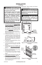
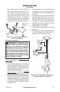
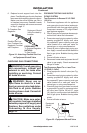
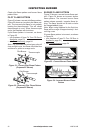
Figure 23 - Removing Log Base
Assembly From Fireplace
Branch
Support
Screen
Screen
Shipping
Screw
Shoulder
Screw
Flexible
Gas Line
Installation Items Needed
• Phillips screwdriver
• sealant (resistant to propane/LP gas, not
provided)
1. To remove fireplace screen, remove 2
screws that hold replace screen in place
for shipping. These screws are located
near top of screen. Discard screws. Lift re-
place screen up and pull out to remove.
2. Remove screws that attach branch sup-
port to replace (see Figure 23). Carefully
lift up branch support and remove from
replace (see Figure 23).
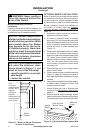
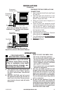
3. Route exible gas line included from re-
place control to equipment shutoff valve
through side or rear access holes in outer
casing.
-
-
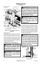
4.
Apply pipe joint sealant lightly to male
threads of gas connector attached to ex-
ible gas line/equipment shutoff valve (see
Figure 24, page 18).
5. Check all gas connections for leaks. See
Checking Gas Connections, page 18.