


26
MR810 Technical Manual Rev C REF 185042601
6
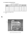
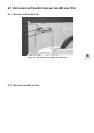
6.5.6 REPLACING THE HEATER PLATE ELEMENT
NOTE: The correct heater plate element is required (refer to Table 9 below).
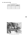
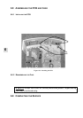
1. Open the case and remove the PCB (§ 6.2).
2. Remove the heater plate (§ 6.5.2).
3. Cut the cable ties attached to the heater plate harness.
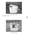
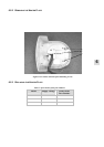
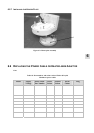
4. Unscrew the six screws holding the backing plate and remove it (Figure 6.8). Refer to Figure 8.2 for
the exploded diagram.
5. Check the heater plate resistance against Table 9. Discard the heater plate element if the resistance is
incorrect (do not discard the mica insulator situated under the heating element).
6. Inspect the mica insulator for any holes by holding it up to the light, and replace it if any are visible
(part number 331 040 114).
7. Ensure the mica insulator is correctly located on the heater plate and place the new element and
backing plate over the top.
8. Screw the heating element backing plate back on with the six screws.
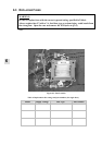
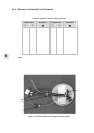
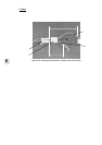
9. Clip three small cable ties (2.5 mm wide) around the heater plate harnesses. Place one close to the
heater plate, securing all wires as they protrude through the top case. Place the second tie halfway up
the wires securing the heater plate harness and protective earth wire (leave the thermistor wires free for
flexibility in connecting to the PCB). The last tie secures th e heater plate harness wires near the Molex
plug. (Refer to Figure 6.7 for cable tie locations).
10. Install the heater plate back into the case top (§ 6.5.7).
11. Reassemble the PCB and the case (§ 6.8).
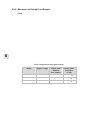
Table 9: Replacement heater plate elements
Model Supply Voltage Heater Plate
Element
Part Number
Heater Plate
Resistance
(Cold)
MR810A-- 230 V~ 043 041 342
353 ± 12 Ω
MR810J-- 115 V~ 043 041 340
88 ± 3 Ω
MR810G-- 100 V~ 043 040 341
67 ± 2 Ω