


MR810 Technical Manual Revision C REF 185042601
25
6
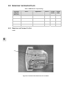
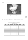
6. Clip one small cable tie (2.5 mm wide) around the heater plate harnesses near the heater plate,
securing all wires as they protrude through the top case. Place a second cable tie near the thermistor
connectors to secure the thermistor wires as they enter the connector (refer to Figure 6.7 for cable tie
location).
7. Install the heater plate back into the case top (§ 6.5.7).
8. Reassemble the PCB and the case (§ 6.8).
6.5.5 REPLACING THE THERMAL CUT-OUT
NOTE: a replacement thermal cut out will be required (part no 349 040 051).
1. Open the case and remove the PCB (refer to § 6.2).
2. Remove the heater plate (refer to § 6.5.2). Refer to Figure 8.2 for the exploded diagram.
3. Cut the cable ties attached to the heater plate harness.
4. Unsolder the two wires attached to the thermal cut-out (Figure 6.8).
5. Remove the two screws holdin g the heater plate thermal cut-out.
6. Place the new thermal cut-out and screw it down.
7. Solder the wires back onto the thermal cut-out.
8. Ensure the thermal cut out has not been tripped by pressing the red reset button.
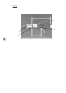
9. Clip three small cable ties (2.5 mm wide) around the heater plate harnesses. Place one close to the
heater plate, securing all wires as they protrude through the top case. Place another halfway up the
wires securing the heater plate harness and protective earth wire (leave the thermistor wires free for
flexibility in connecting to the PCB). The last tie secures th e heater plate harness wires near the Molex
plug (this tie may not need to be cut to replace the cut out). Refer to Figure 6.7 for cable tie locations.
10. Install the heater plate back into the case top (refer to § 6.5.7).
11. Reassemble the PCB and the case (refer to § 6.8).
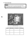
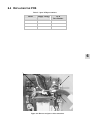
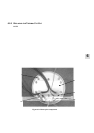
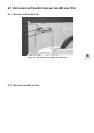
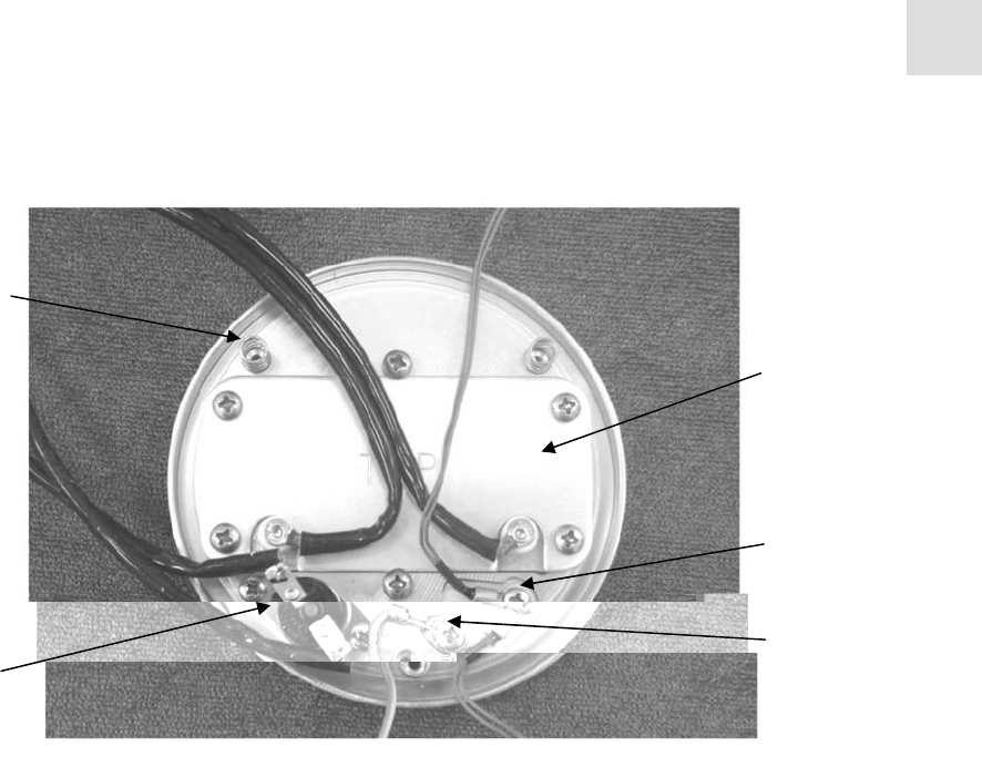
Figure 6.8: Heater plate components
Main Thermistor &
Backup Thermistor
Protective earth
connection
Thermal
cutout
Backing plate
(heater plate
element underneath)
Heater
plate
springs