


12
MR810 Technical Manual Rev C REF 185042601
3
3.4.3 "SEE MANUAL" INDICATOR
The "See Manual" indicator displays two fault types:
Hardware Fault. The "See Manual" indicator flashes off and on. Briefly pressing the Temperature Setting
button briefly produces a pattern on the three Temperature Setting Indicators, representing a fault
code. Refer to § 5.2 for fault code defi ni t i ons.
Microprocessor Fault. The "See Manual" indicator is on continuously.
3.4.4 HEATER-WIRE INDICATOR
The Heater-wire Indicator is located in the connector at the end of the heater-wire adaptor. If the heater-
wire adaptor is connected to a compatible heated wire circuit then the green indicator will illuminate, and
the heater-wire mode of operation is initiated.
If a heated circuit is connected and the Heater-wire Indicator does not turn on then a fault is present in either
the heated circuit or the heater-wire adaptor, and non heater-wire mode of operation will be in itiated.
Refer to § 5 for trouble shooting.
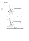
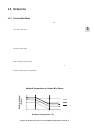
3.4.5 AMBIENT TEMPERATURE SENSOR
Measures ambient air temperature for controlling the heating of the heated wire breathing circuits. Refer to
§ 3.5.1 for m or e inf ormation.
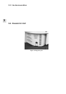
3.4.6 CHAMBER DETECTION SENSOR
A thermistor is embedded in the third pin in the heater-wire connector. This thermistor senses the chamber
type (reusable or single-use) by measuring the temperature of the gas exiting the chamber as it passes
through the circuit elbow.